|
|
|||||||||||||||||||||||||||||||||||||||
Ballast Sled
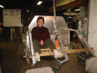
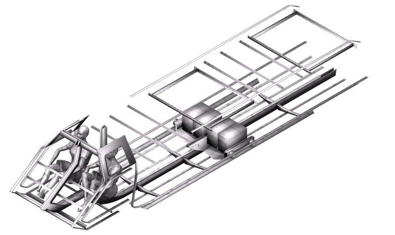
There is water in the shop so Spring must be coming soon, and I am starting to build the Ballast Sled with is really the heart of the boat. (1) (2) (3) The ballast sled is 2000 pounds of batteries and lead inside an aluminum box that is moved forward of aft on wheels with the help of an electric winch. When the boat submerges all of the space behind the cabin will flood leaving 26.8 cubic feet of air in the cabin. The sled will be moved forward to keep the cabin from pitching the boat up. On the surface the sled will be moved aft or backwards so the has a slight up angle in order for it to plane under the power of the engine and jet pump. The ballast sled will weigh about 2000 pounds, consisting of 8 batteries and lot of lead.
2000 Pounds! Can that be right?Until it's in the test tank we will not know for sure, but it will be close. The cabin volume is about 26.8 cubic feet. Sea water weighs about 64 pounds per cubic foot, so the total cabin displacement is 1,717 pounds. That would be enough ballast if the sled was directly under the cabin, but since it is behind the cabin the boat naturally wants to pitch nose up. So it is necessary to maintain a displacement volume at the stern of the boat to counter balance the rotational force. However adding lift at the back of the boat means that the sled needs to balance with that displacement too. Think of the ballast weight as a fulcrum under a beam that must be kept level. There is a large weight on one end of the beam and the fulcrum is 2 feet from the large weight. To keep the beam in balance we add a small weight about 8 feet away on the other end of the beam. The total weight supported at the fulcrum is equal to both weights. So the engine compartment at the stern of the boat along with a ballast tank, will displace about 200 pounds more than the weight of the engine. That brings the total to 1917 pounds, but we can deduct the weight of the hull forward of the ballast sled. The entire aluminum structure will be about 1300 pounds and perhaps 300 of that is the cabin and just aft of the cabin. So that cuts the number to 1617 pounds. The weight could be less if we never left the cabin, but the calculation has to be done assuming both occupants have exited the divers hatches. I also need to consider that sufficient downward force is needed to keep the boat firmly on the bottom when it is empty. I don't want it to be blown away by the current so we likely need to add back 100 pounds. As you can see, all of the numbers are really only estimates and there are a lot of considerations. I can't accurately predict the final cabin volume, it's center of buoyancy, the center of mass for the ballast sled, the final distance of the sled in relation to the cabin, the displacement of the engine compartment, etc, etc. So instead I plan to increase or decrease the weight of the ballast sled as needed, just like a diver does when getting in the water with a new wet suite.
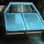
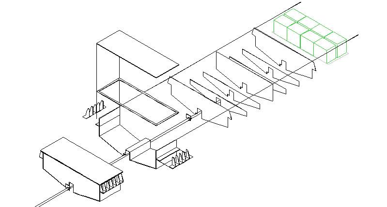
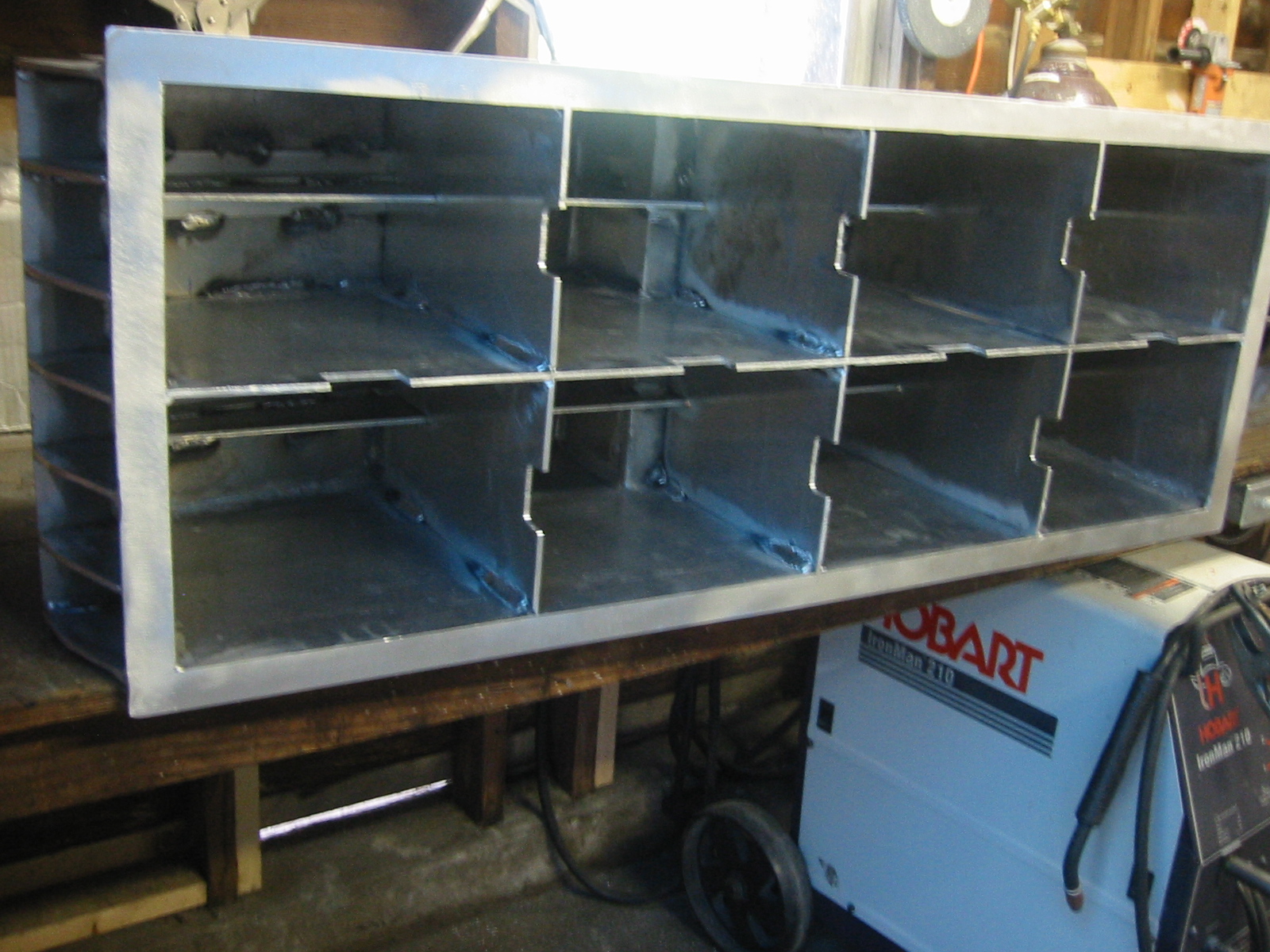
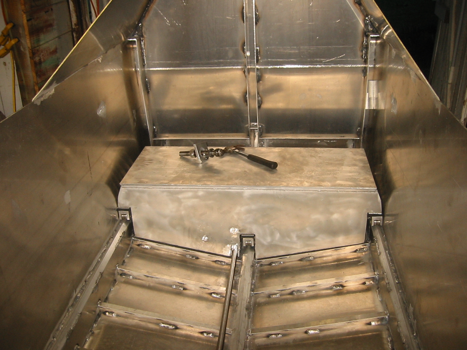
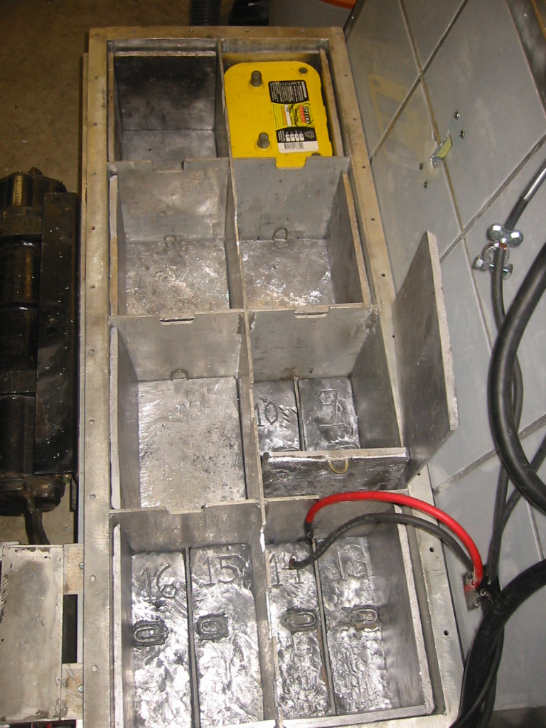
(4) The design for the sled changed a little more while it was going together because it was impossible to weld the long cross frames to the bottom with only 2 1/2 inches between each frame. I could have started at the front or back side and worked toward the other side but I would not have been able to weld on both sides of the outside frames. Since the box is water tight I wanted to weld both sides, so instead I dropped two of the shorter frames from the design. Even then I had to weld angle to the bottom of the two remaining short frames so that it was possible to weld them to the bottom of the sled. (5) The sled rides on 3 rails make from 1/4" Aluminum angle. Its 30, 1.5" stainless steel wheels are grooved to fit the angle and housed in 9 cast aluminum blocks which use foam suspension to allow all of the wheels to remain in contact with the rails to compensate for irregularities and flex in the hull. (6) The 6 deep cycle batteries weigh 44 pounds each and the 2 starting batteries at 39 pounds each for a total of 342 pounds. That is about 350 pounds with the rack, leaving 1,581 pounds of lead to reach the total of 1,931 pounds required to overcome the displacement of the cabin when no crew is on board. The numbers look accurate but I only hope that reality is within 10% of the calculation. Since lead is 700 pounds per cubic foot the 1,621 pounds will require only 2.32 cubic feet, or 4,009 cubic inches. Most of this weight will be carried in the bottom of the sled with the batteries riding on top. Additional lead blocks have been inserted in the gaps between the batteries and when needed more blocks will be bolted onto the outside of the box. Details about the lead are here: Pouring the Ballast Sled A 1 inch flange warps around the top opening to the box and a the
lid is be bolted to the flange with a neoprene gasket between.
Power cables will be constructed from welding cable and be sealed
with epoxy where they penetrate the box.
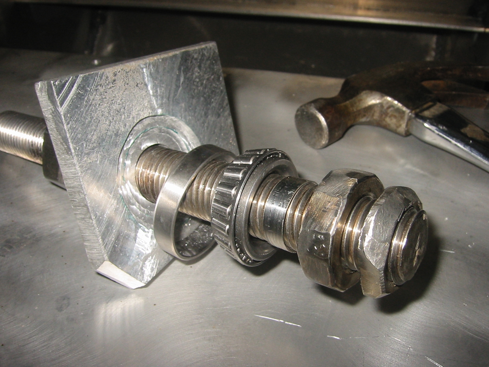
Details are here: Battery
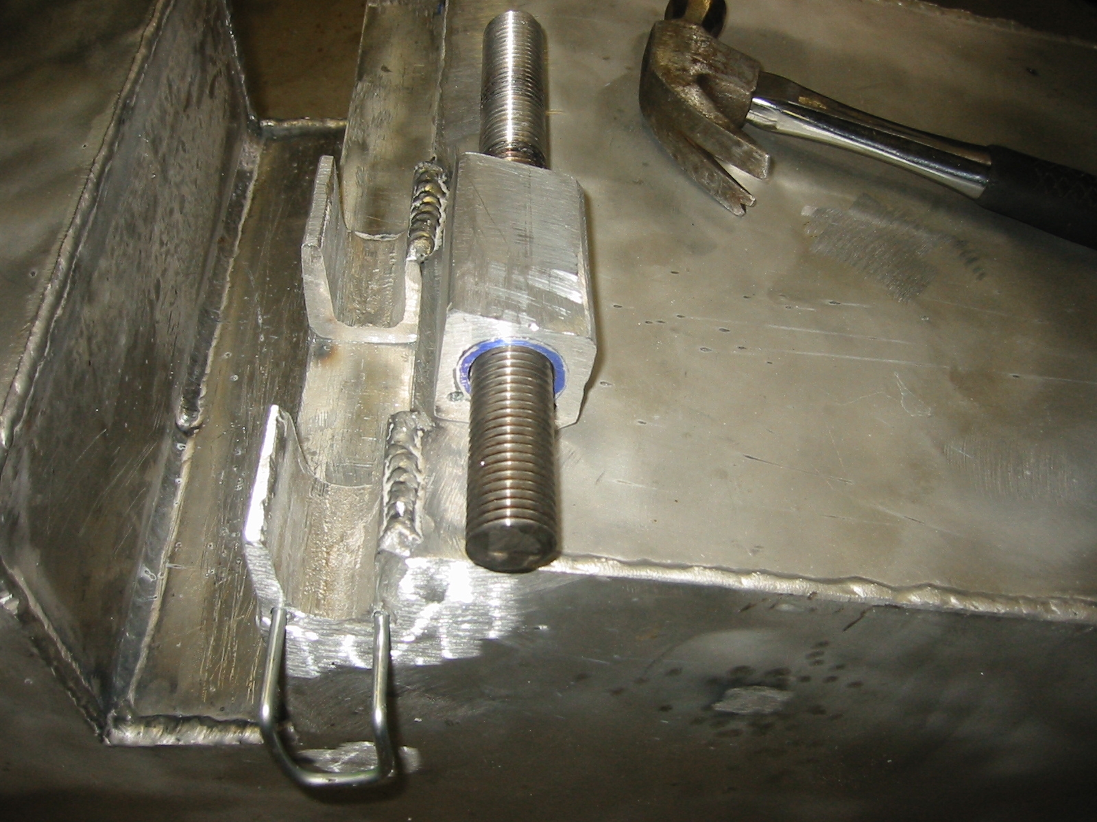
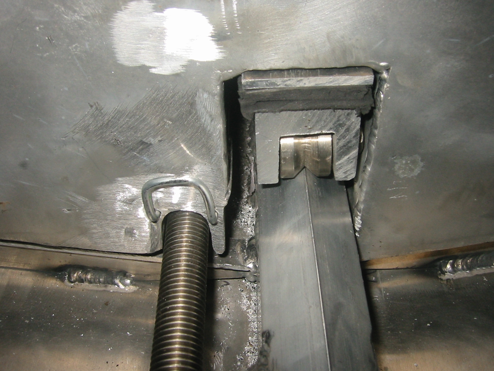
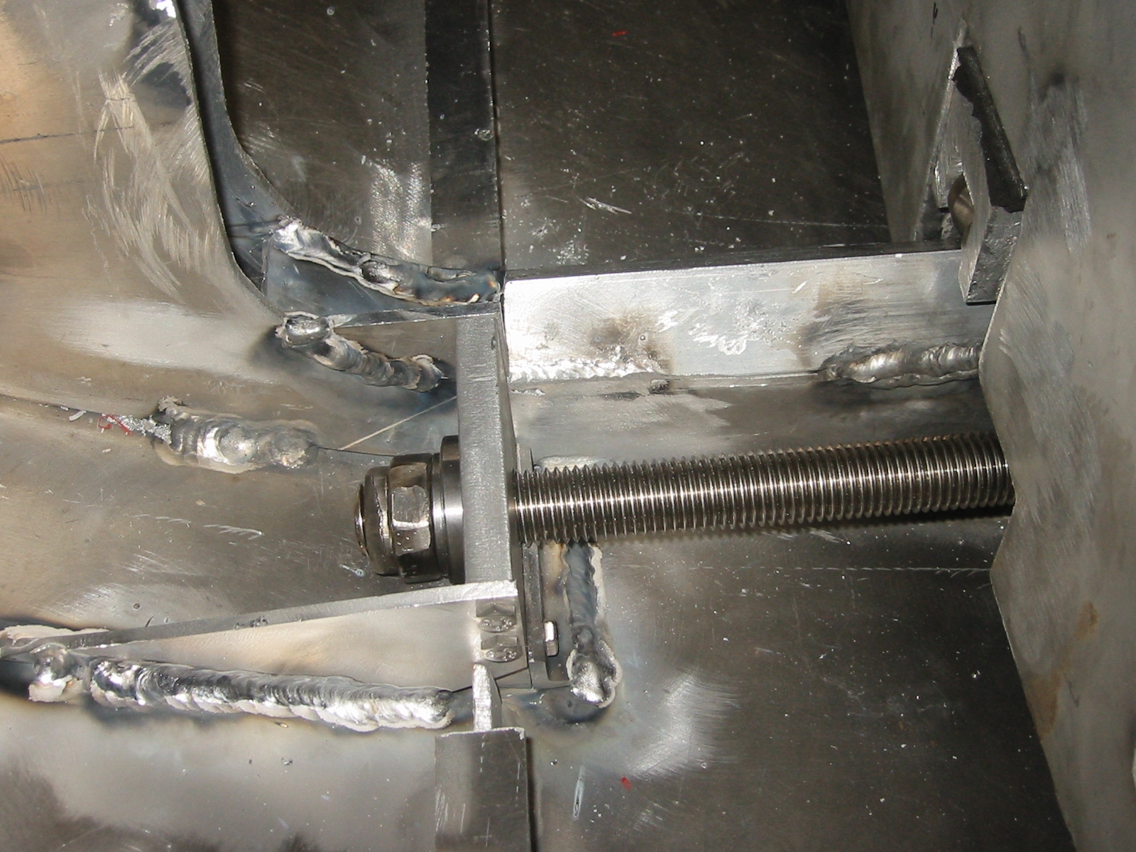
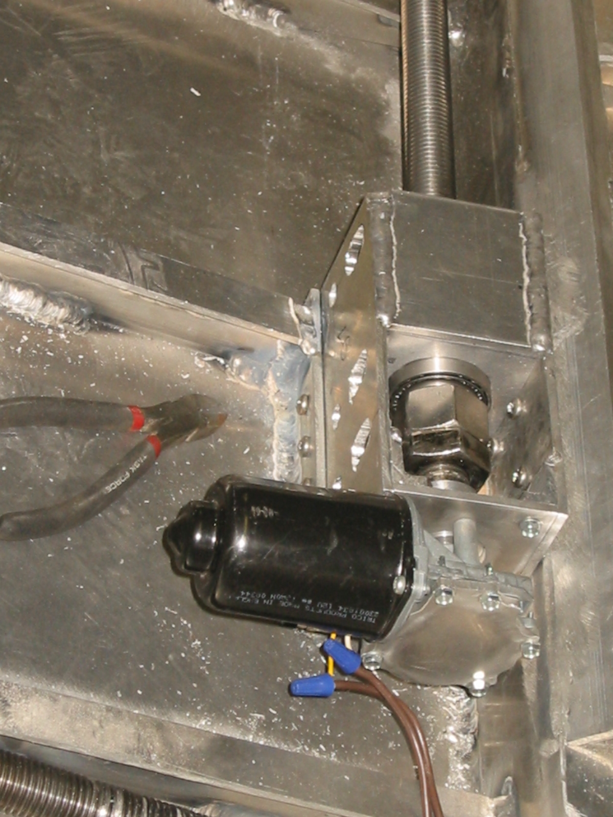
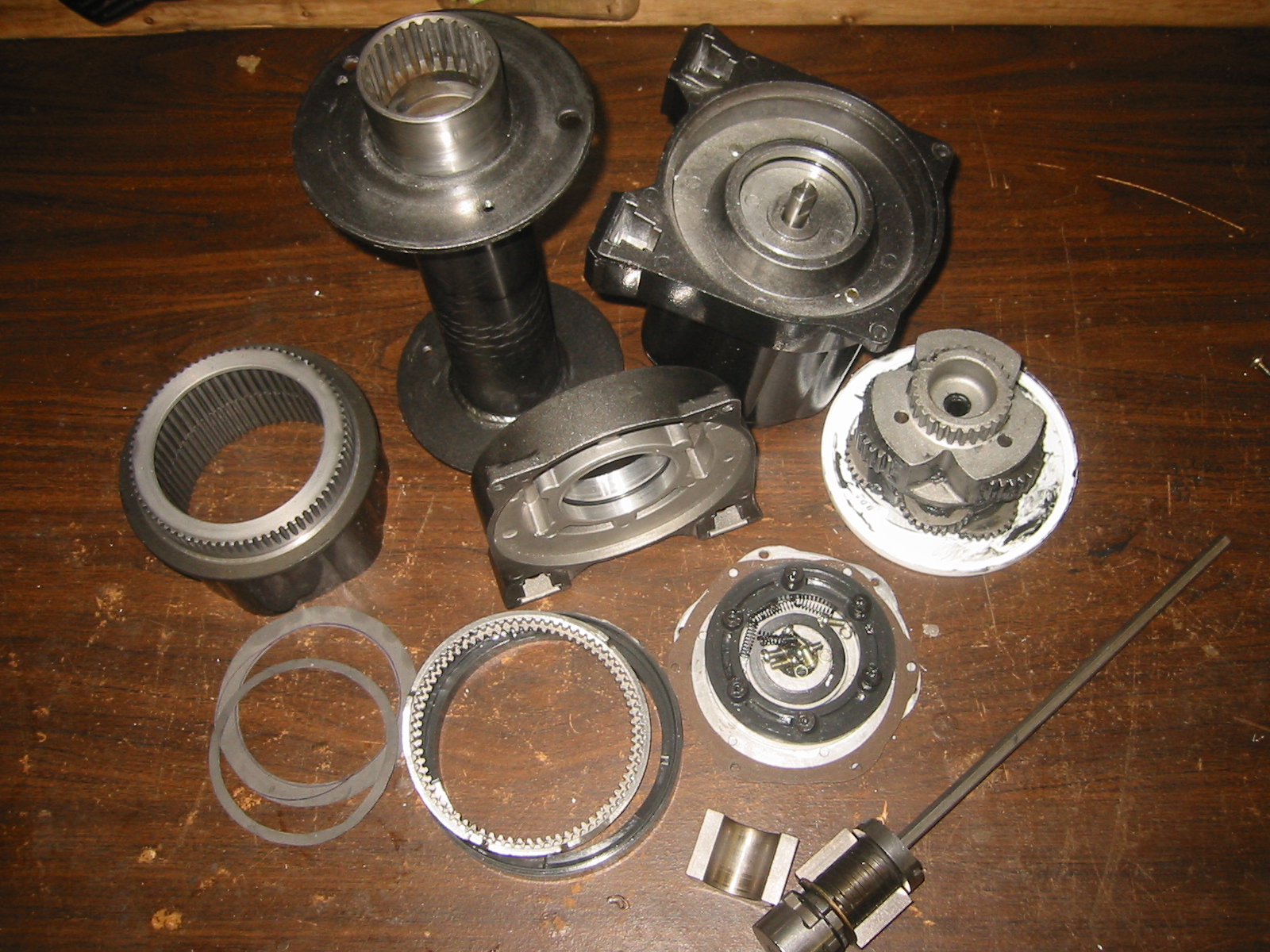
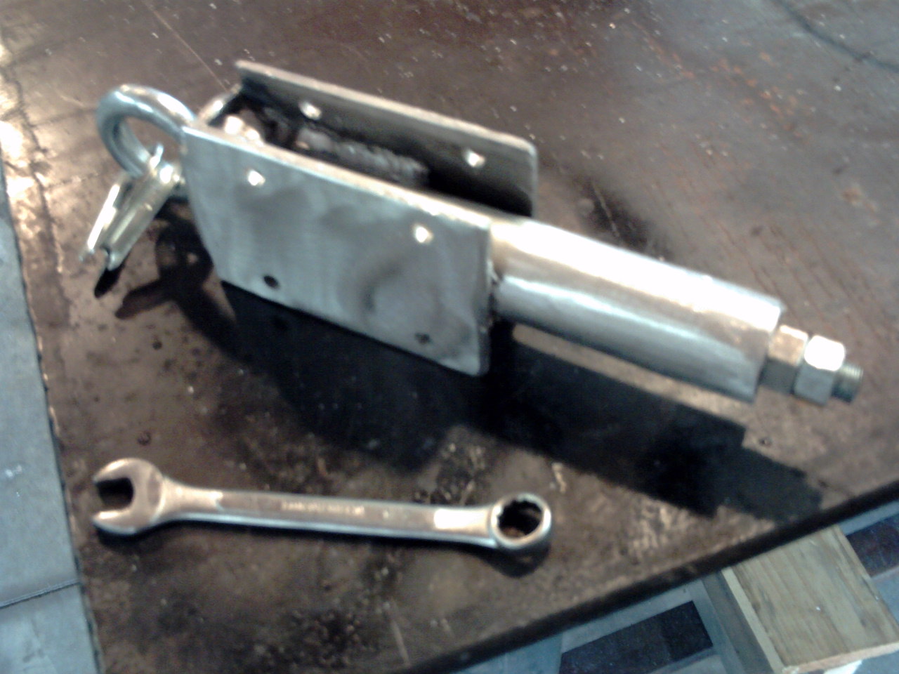
and Charger. Testing a Lead ScrewThe sled also needs to connect to either a roller chain or lead screw so it can be moved along the rails. (7) I have my doubts about the reliability of a lead screw especially in a salt water environment, but it would be the safest approach because even if one end of the screw were to break free it would still restrict the movement of the sled. If a chain or cable were to break, you can imagine the potential for damage from a 1 ton weight freely rolling back and forth inside the hull. Unfortunately lead screws are expensive. A 1 inch x 12 foot, 5 thread per inch, 18-8 Stainless Steel, lead screw from McMaster cost $290 plus $90 for a bronze nut. The treads on lead screws are cut so as to reduce friction, but if I can generate enough tork to overcome the friction of normal V threads then I can use all-thread and save a couple of hundred dollars. 1"-8 thread, 12' length, 18-8 stainless steel threaded rod cost only $105. (8) The path for the all-thread was constructed into the bottom of the sled beside the center rail. An 1 1/2 inch piece of aluminum angle forms this portion of the sled bottom. The lead screw nut is actually a stainless steel nut and short section of aluminum pipe cast into a block of aluminum designed to fit the notch on the bottom of the sled. You can see details of casting this part on the "Casting Aluminum" page under Using Aluminum as a Mold. Two 'U' shaped cast retainers trap the lead screw nut in place and two 3/16 inch steel pins lock the nut to one of the retainers. This allow the sled to be unlocked from the lead screw so that it can be removed from the hull without removing the lead screw. (9) It's a good feeling when all of the little parts start coming together. With the lead screw nut completed, the sled could be set in place on top of the carriages which hold the stainless steel V grooved wheels. Details for the wheels are on the Lathe page. The carriage wheel sets have foam rubber between them and the sled to absorb shock and allow the wheels to adjust to the track. I still need to add plates to the sled in front of and behind the carriage wheel sets to insure they remain in place should the sled possibly be bounced high enough off of the track. Not likely once the sled contains the 1600 pounds of lead and batteries, but I'd rather not take the chance. (10) Stainless steel ball bearings are expensive, so I am going to experiment with standard $6 wheel bearings from the auto parts store. Nothing like going to the corner auto parts store and asking for wheel bearings and telling them that the make and year don't matter, you just want something with and ID just over 1 inch. The guys at my parts store are slowly getting use to me, but we have a way to go. In truth these guys are a great source of information, tips, and tricks because most are going to school to become mechanics, welders, and machinist, and they are happy to share their knowledge when there is not a line of customers. The bearing are mounted in a plate is 1/2 inch aluminum cut from the Chevy engine mount that came with the pump I purchased. A recess was routed into it for the outer bearing raceway. The bushing to go between the inner raceway and the threads started as a nut and was ground down and then turned on the lathe. The lock nut set is another 1 inch wide nut that was cut in half and then rounded with addition sides. The outer most lock nut only has 2 flat sides and is rounded. This is the forward bearing set and all of this was done to allow the lead screw to be mounted as far forward as possible. (11) The bearing mounting plate was then bolted to supports which were welded to the hull. (12) Another bearing set similar to this one will be at the rear where a converted windshield wiper motor will be mounted to drive the screw. I got the lead screw drive motor mounted in place and work great for moving the ballast sled as long as their is no more then 200 pounds of weight on the sled. So my windshield wiper motor idea will work fine for
extending and retracting the landing gear, but as expected the sled
is going to need something with more oomph. Unfortunately I got to
looking at larger drive motors and 1+ hp units are a big jump in
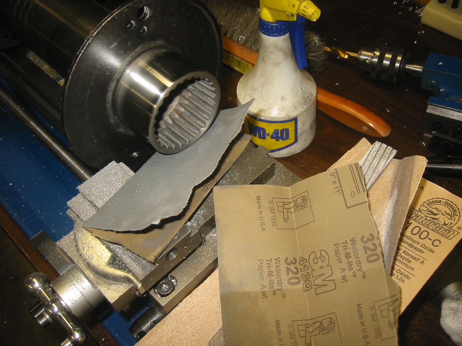
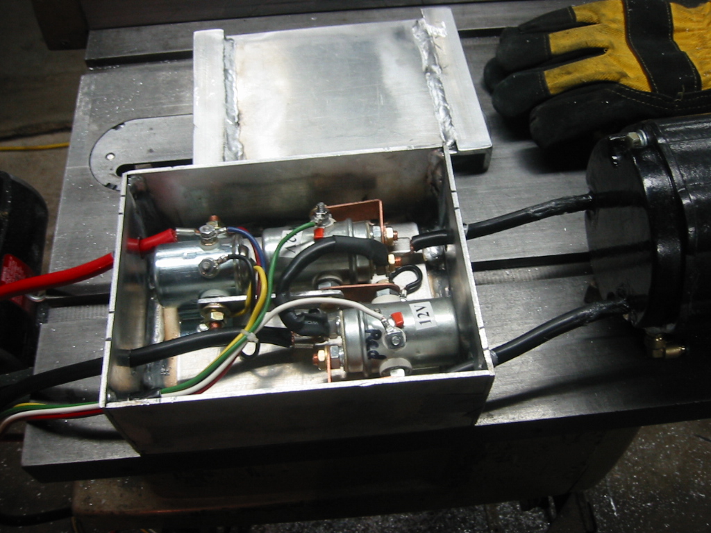
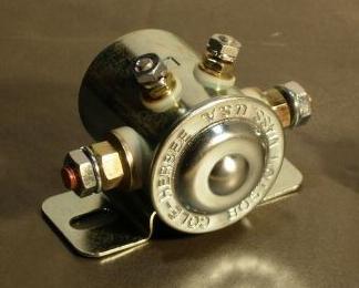
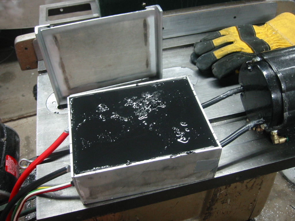
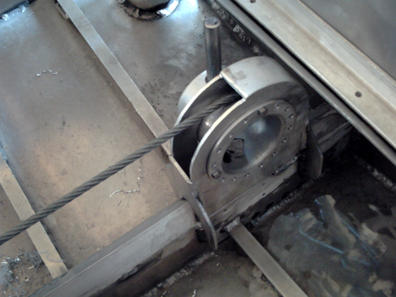
price and weight. Using a Winch to Move the Sled(13) As an alternative I am going to look at converting a 12 volt winch for the job of moving the ballast sled. A winch can be mounted onto the sled where the weight will be an advantage and the cable can be reconfigured to move the sled front to back. I just so happens that Harbor Freight has a 4 ton winch on sale for $240. (14) Fortunately converting the winch to work under water is not that hard to do. I machined a pair of aluminum bushings for each end of the spool so that an o-ring could be trapped between them. I also removed the leaver which disengages the spool from the gear box and allows the spool to freely turn because I would not need the feature and it would be impossible to make water tight. With the addition of a couple of gaskets and some silicone sealer, the gear box was permanently engaged. The motor housing is already sealed nicely. I welded one small hole in the spool shut. (15) I placed the spool in the lath so I could polish the ends up so they would seal nicely in the o-rings. To polish the ends I started with a flat file and then worked down through sand paper grits to very fine wet/dry paper. The drive shaft from the motor on the opposite end of the spool also features a break that locks in any time the motor is powered off. The motors drive shaft is sealed and connects to the brake which connect to the drive shaft inside the spool which travels to the other end where it enters the gear box. The gear box provides a 210:1 gear ratio using a series of planetary gear sets and then delivers the torque to the spool through a spline connection in the end of the spool. The gear box is filled with a heavy grease and there is no seal between it and the inside of the spool. I made an aluminum bung and welded in onto the end cover plate of the gear box. I could fill the gear box and spool with oil then replace the 1/2 inch bolt in the bung with a rubber bulb filled with more oil. By doing so, as the water pressure increases, so will the internal pressure of the oil thereby preventing water from forcing it's way around the o-ring seals. Alternatively it made more since to compensate the winch and the battery box with ambient air. An air line will already needs to extend from the cabin to the engine compartment so it will not be inconvenient to tee into the line with a small flexible hose. This will allow the motor brushes to operate in air and not oil which should prevent any damage that may be caused by the oil. (16) The spool on the winch will take-up cable from the direction of travel and play it out in the other. A large coil spring will be used to maintain tension on the cable, but it is important that the total length of cable remain as constant as possible. The problem is that the speed of the cable increases as the number of coils around the spool increases. To prevent this I cut a 5 inch pipe apart and welded back together around the existing spool. The new spool is divided into two hales and is now large enough that it can hold 11 feet of cable around each half. Since there is only one layer of cable on the spool the speed will be constant and the amount of cable taken up will equal the amount of cable played out. The extra diameter will reduce the winches maximum tork, but since 8,000 pounds is considerably more and what is required, it will be better to have the additional speed in place of the tork. (17) The electronics on the winch consist of 2, power switching solenoid relays that control direction. (18) I added a third relay Single Pole Single Through on the positive lead for added safety. This relay will allow power to be disconnected with an on-off toggle switch in the cabin, just in case one of the other relays sticks on. Since this is an 8000 pound winch I want to be able to shut it down before it rips the hull apart. The relays were mounted onto an aluminum plate that was connected to the ground lead, and then housed in an aluminum box, but the relays and the plate they are mounted to are isolated from the housing box with potting. This will allow the hosing to be attached to the hull but not allow the hull to be part of the electric circuit in order to avoid galvanic corrosion. Read more a about (19) You can buy real potting compound for around $50 a pint. I need at least 3 pints in this box, but that is only about $4 in DIY potting compound. The mixture is 1 part polyethylene plastic melted into 4 parts of regular paraffin wax by weight. This raises the melting point to about 170 degrees and makes the solid compound significantly harder than normal wax, so it is resistant to summer days as well as water pressure. Read more a about machineable wax
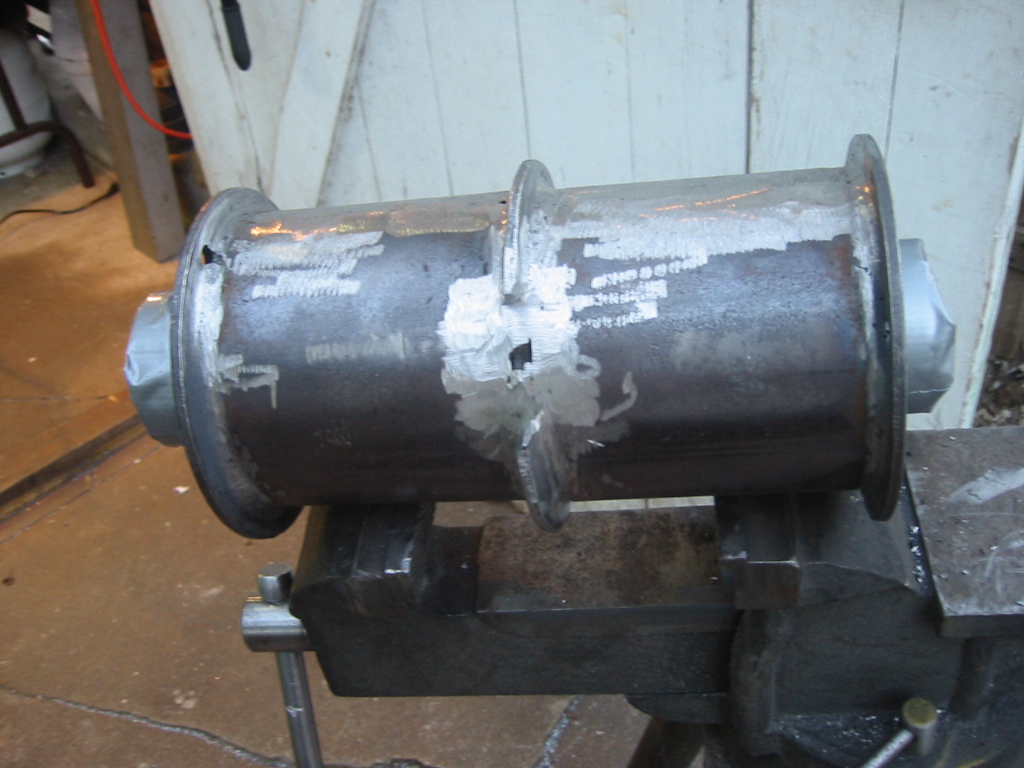
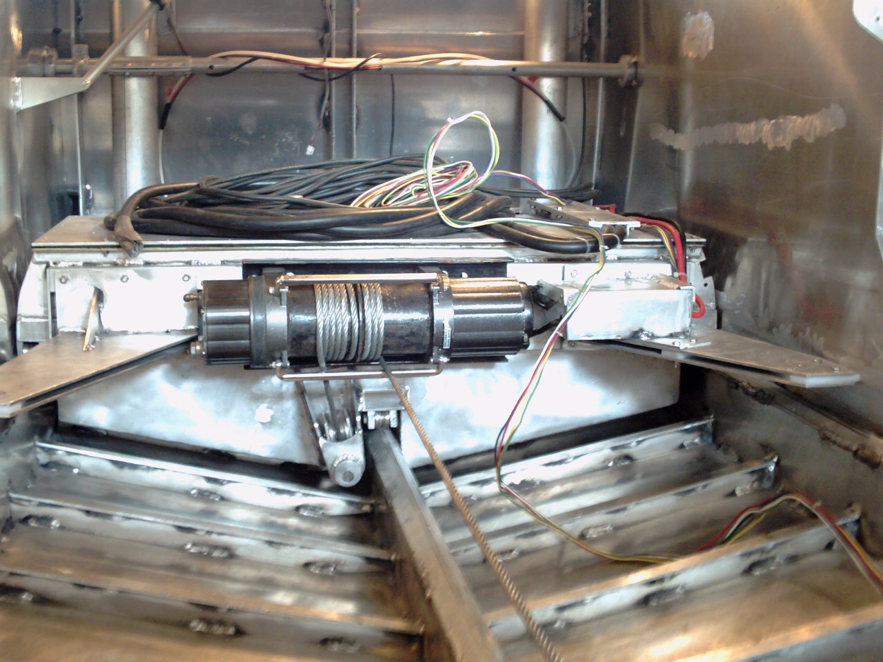
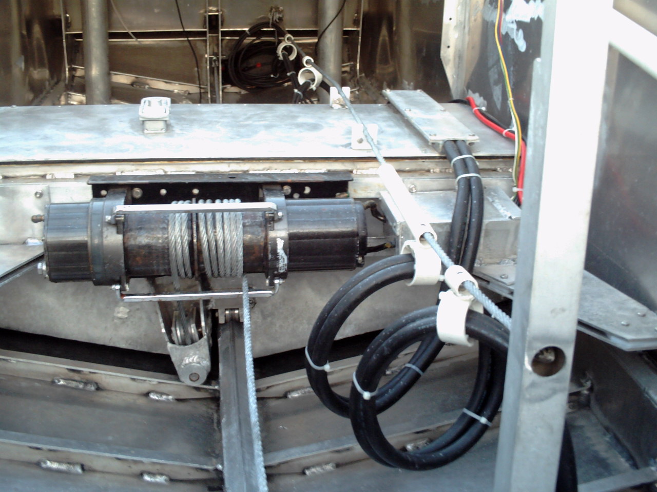
here: Lost Wax Casting (21) Fall back in time, It's April 2005 and my son is off training before he is deployed to Iraq. So I am training my wife as my new shop helper. The deal was that I take dance lessons and she works two nights a week in the shop. There is also some plans now on the table for building an aluminum catamaran over the next 8 years. Seems like a good way to put these new skills to good use. (22) The winch and the relay box are mounted to the ballast sled and pulleys are mounted to route the cable under the sled. The pulleys assure that the pull will be as close to the center of the sled as possible in order to help the sled to track smoothly. In the photo, a piece of extension cord is used to test the pulley alignment because getting the real 5/16 inch cable to pull stright will require a lot of tension. A spring will be used at on end to keep tension on the sled and to help absorb some shock.
The next step was to install the batteries. You can read more about that here: Battery and Charger.
Sled Installation and Testing
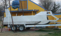
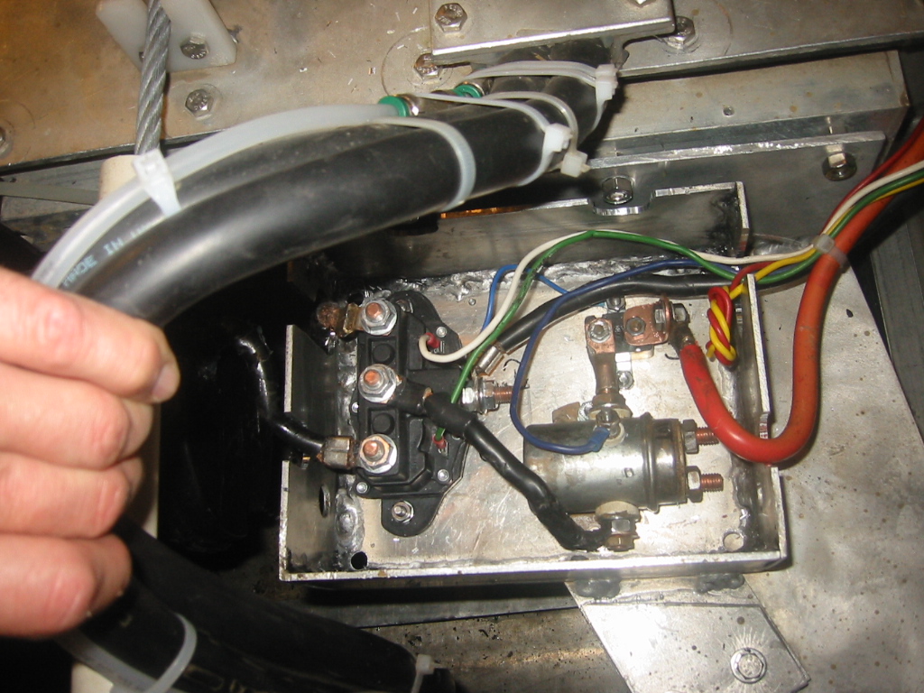
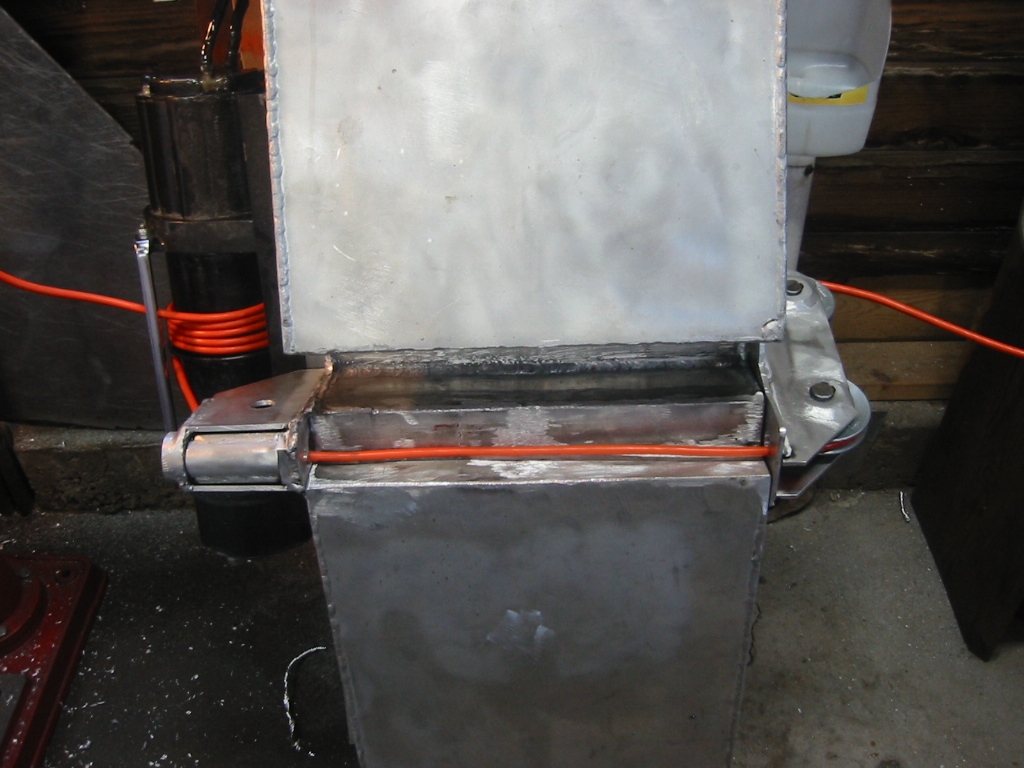
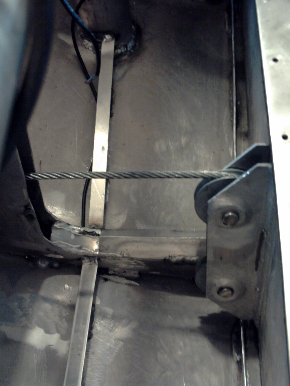
(1) The ballast sled along with the lead ballast and batteries is now installed in the hull. As anticipated the sled did not want to travel cleanly down the tack being that it much wider than it is long. Instead it yawed enough to make contact between the wheel blocks and the side of the hull. To correct the problem skid plates were added on each corner and the wheel blocks where bolted to the mounts in order to keep them in place. The skid plates are bolted the the sled and nylon, aka cutting board, is used to contact the side of the hull. (2) The cable is anchored to a spool at the aft end of the track. The spool is held in place by a pair of 1/4" bolts and can be used to take up slack on the cable or easily release the cable should it be necessary to manually move the sled. (3) (4) The cable simply wraps around the drum of the winch and passes on through pulleys to the other end. The cable needs slight tension on it so that it grabs the drum so I started with a spring tensioner where the cable connect to the forward cabin frames but the addition tension proved unnecessary as the wraps of the 3/8 inch cable around the spool proved to provide sufficient friction. (5) The power cables are festoon from a piece of cable that is stretched from the the back of the cabin wall to a brace that is just forward of the engine compartment. We first tried hanging the power cords from the steel cable using nylon hangers that Kay meticulously cut from kitchen cutting boards but they would bind on the steel cable when they rotated as the power cable coiled up. The answer was swivels that rotate and allow the power cords to coil and uncoil.
Sled Winch Repair
|