|
|
|||||||||||||||||||||||||||||||||||||||||||||||||||||||||||||||||||||||||||||||||||||||||||||||||||||||||||||||||||||||||||||||||||||||||||||||||||||||||||||||||||||||||||||||||||||||||||||||||||||||||||||||||||||||||||||||||||||||||||||||||||||||||||||||||||||||||||||||
Building the HullMaterialThe aluminum was arrived! Just over 1 ton of various 3/16 inch thick sheets, two of which are 6 x 20 feet and weigh over 300 pounds, plus angle for reinforcement. My order came from MetalSalesUSA in Louisiana, even though I could have purchased locally, availability and the price including the shipping were lower when ordering from a company that routinely supplies boat builders. I latter priced some more material from MetalSalesUSA and the prices were much higher that other suppliers, so the I would always recommend shopping around. All of the sheets arrived strapped to a frame work of 3 - 4x4's and planking so I gladly splurged and rented a fork lift for $150 including operator and helper. Once the skid was off the truck the fork lift was able to slide it down our narrow drive way and into the backyard. Individual sheets can be dragged off of the stack and onto 2x4' where they can be cut before moving them into the assembly area. All of the material is 5000 series aluminum designed for marine use. Two of the 4x20 ft sheets are 5086 H116 which is a harder and more expensive alloy that the 5052 H32. There were intended to be used for the bottom hull an only by luck did this actually happen, because my fist mistake was to forget that two of the sheets where 5086 H116. Lucky they actually got used cut into the correct pieces. I learned that you identify the sheets based on a color code painted onto the end edge. It turns out that using 5086 H116 for the bottom hull only made bending it to form the bow more difficult. In hind sight I would likely dispense with using 5086 and only use the cheaper 5052. That would not be the case if I were building a river boat and indented to frequently bounce off rocks, but as a submarine my worst nightmare is a surface vessel that ignores the dive flag that will be surfaced before I surface my sub, and proceeds to run his keel across the top of the cabin. Now that I have had a chance to work with 3/16 inch 5052 I feel fairly confident that I will win any battle with a fiberglass hull.
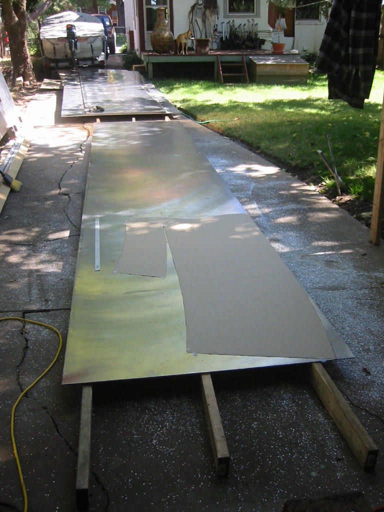
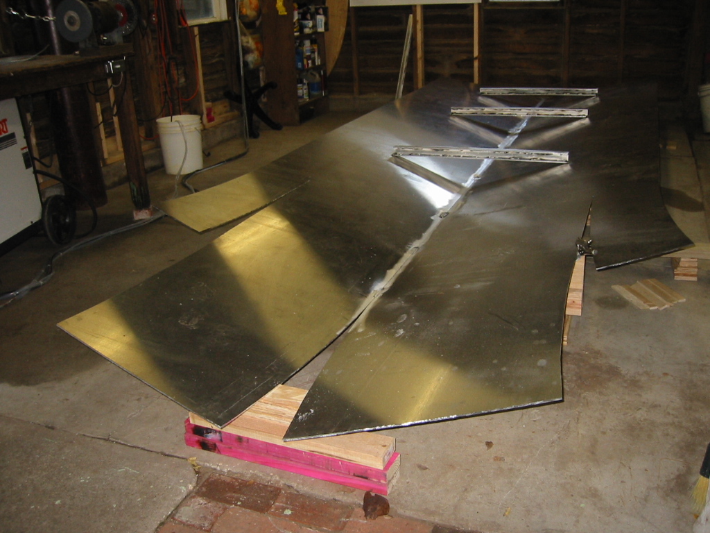
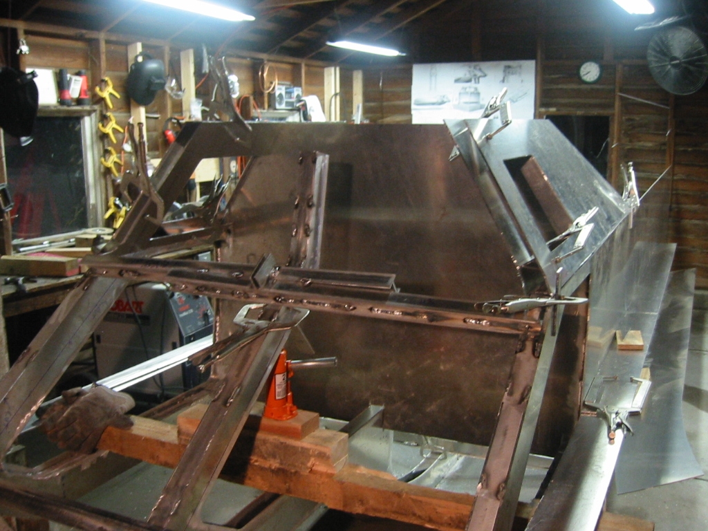
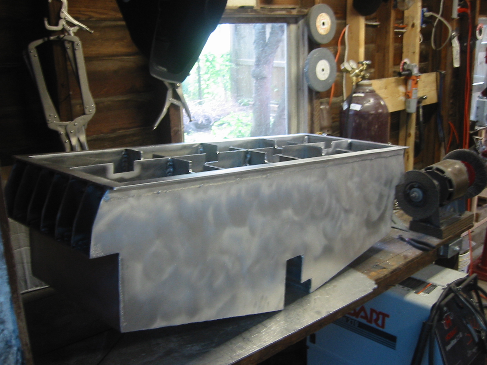
Laying Out the PatternBefore the sheet is marked it is dragged out of the stack and onto 2x4's so it is laying flat. The 2x4's will also act as saw horses. The blade of the skill saw is set so that it only protrudes about 1/4 inch thought the sheet, so there is no problem cutting over the 2x4s. Since I need two copies of most pieces and the aluminum is the same on both sides, I can stack up 2 sheets and cut both parts at the same time. I did not have the guts to do this with the large sheets because I wanted to limit the damage if I made a mistake. The second option is the use the first piece cut as a pattern to mark the second piece, and that works nicely. The CAD drawings created using TurboCAD where plotted onto paper by a company that normally plots patterns for making sails. I tried transposing the design just using the measurements for the drawing, but the curves are very time consuming making the $40 spent on the plotting a great investment. The plans are not complete nor did I have every drafted part plotted. I only did the parts with curves and almost every thing that formed the framing for the cabin. The CAD drawing and the patterns are also not intended to be the final shape. I'll make small adjustments and changes that I did not care for or foresee to make in the CAD drawings. So some of the patterns, such as the rear bulkhead of the cabin will be more for a reference check and for actual size. Having never seen the parts of a boat laid out it was not possible to see how the pattern would form a bow, so I first tested the pattern on a on sheet of masionite and formed it over a plywood frame. This helped provide the required confidence to made the fist cut. An equal amount of anxiety must be over come to start the first weld. The two bottom hull sheets are now tacked together and its starting to look like a boat.
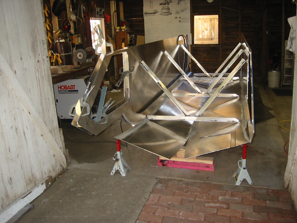
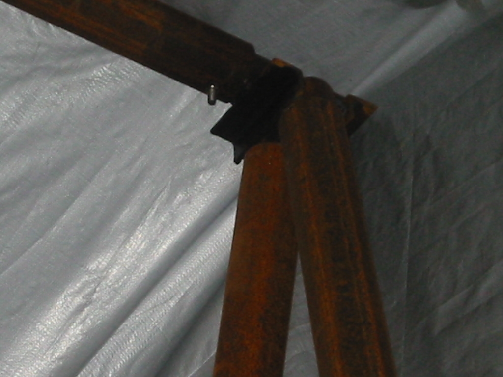
Hull CradleI considered building a set of round frames that set atop rollers so that the hull could be rolled while it was under construction, but decided to use simpler plywood blocking and just leave much of the welding until the boat can be dragged out onto the lawn and rolled over. The plywood frames are cut with a 12 degree angle for the dead raise and then blocked and shimmed to proper alignment. After the sheets were laid on the blocking the blocks were leveled and the sheets were welded together with several 2 inch welds. Temporary cross bracing was used to help pull the sheets together and provide extra support. The plan is to set all 6 of the
longitudinal frames in place that come forward into the cabin. Those
will then support a winch that will bend the bow into shape. Temporary bracing is added in order to maintain the shape of the structure before additional welds are added. A cradle with a 12 degree angle was made in order to easily assure that the sides are properly aliened with the bottom before the temporary braces are tack welded in place.
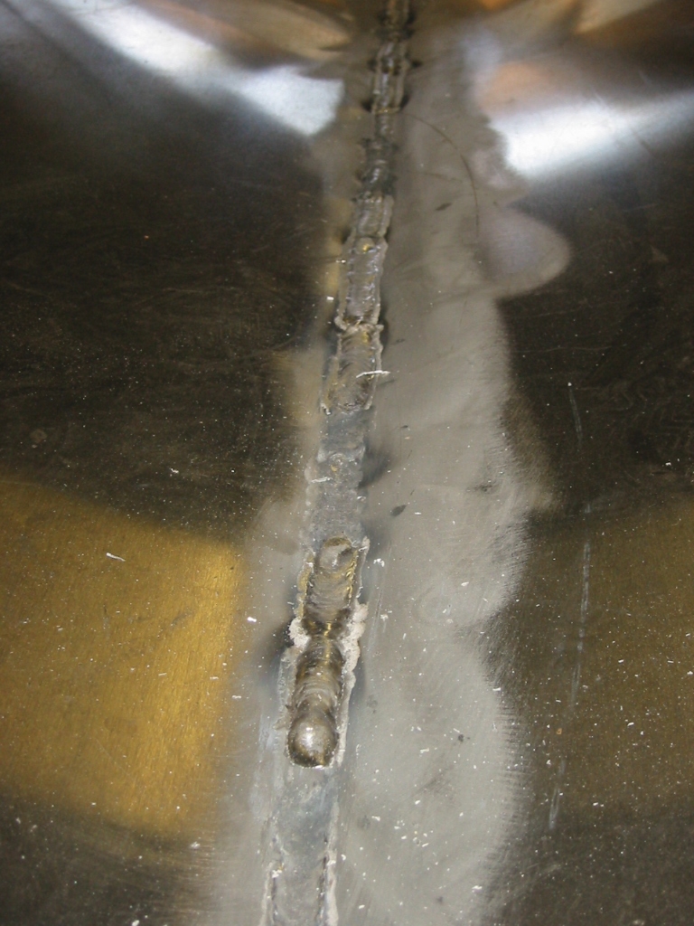
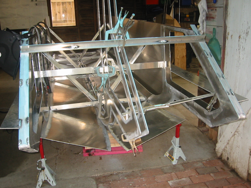
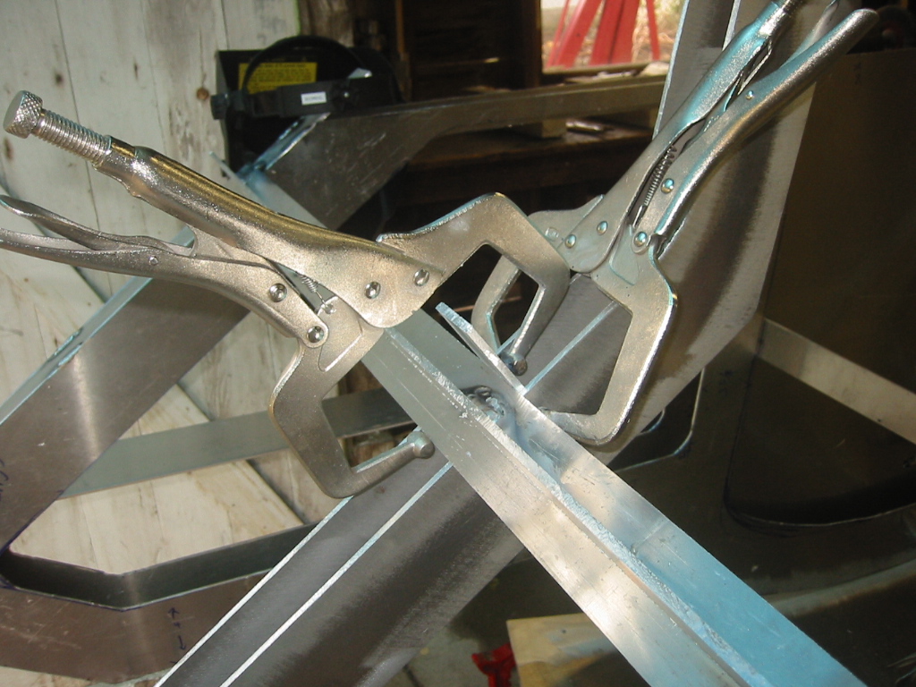
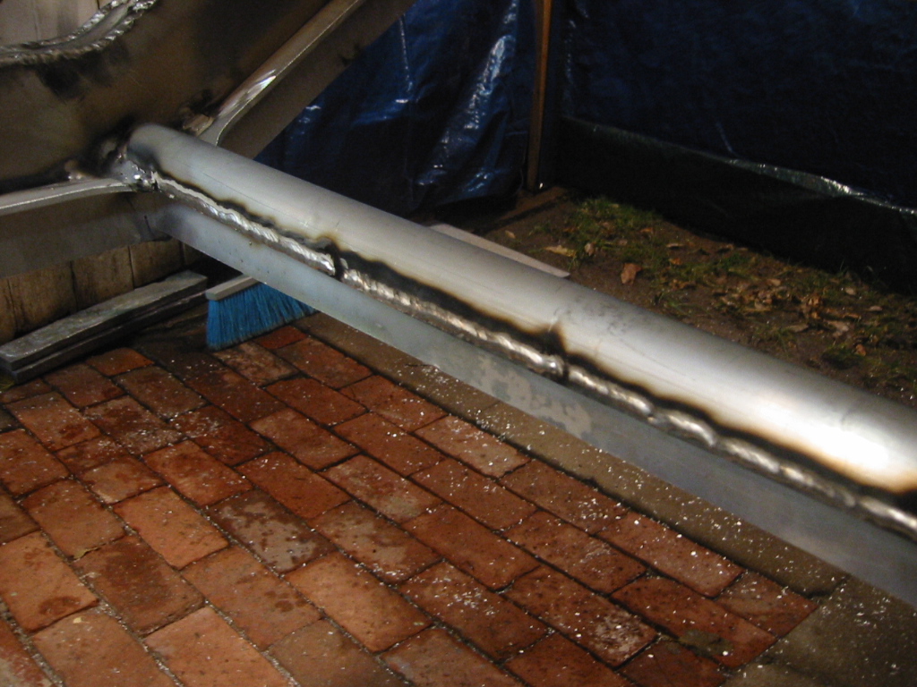
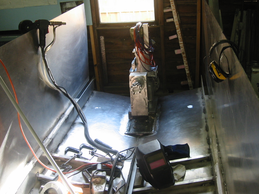
Welding Stuff TogetherAny welds that will not be covered up by the next piece will not be completed until final welding or just before they are enclosed in order to reduce the amount of overall distortion to the frame. The idea is that the addition of additional structural components will reduce some of the warping caused by welding. Because the frame is held together will relatively few welds any serious distortion from welding on new parts will break some existing welds with a loud BANG! That your cue to find the weld that just broke and to do what you can to reduce the stress your causing, such as letting the part cool down. (2) So the bottom center and the inside of the sides of the hull are completely welded before the inside frame are added. The sides are welded to the bottom hull with 2" welds with 4" skips, and the bottom is a solid weld but completed in 3 to 6 inch segments. It is important to move about the structure and add only two or three welds in any one area in order to prevent heat buildup and reduce deforming the structure. (4) There is only 1, 5/8 inches between the frame which are 5 inches deep, so welding inbetween the frames is not possible. (5) A temporary strongbacks were added to each side hull to assure alignment while the webbing is being stitched in place. Once the webbing joins the side hull to the frame the two pieces become very stiff. (6) The center frames came next. (7) Clamps and temporary cross bracing are the order of the day. With enough clamps even large pieces can be completely dry fit. (8) (9) The webbing between the frames is tacked into place and then bent to the shape of the frame. Heating with a propane torch in addition to hammer persuasion is necessary for the sharper bends.
Bending the Hull to the Frames(1) With the center frame in place I figured it was time to bend the bottom hull up into shape. The first part of the bend can be done by hand and a couple of jack stands will hold the bend while the hull is tacked to the frames. (2) A 2x4 is then used to further bend the hull up to the frame and a few more welds are added to again hold it in place. (3)Then notched pieces of sheet are used to hook onto the end of the hull sheet so it can be clamped into place against the frame while additional welds are added. This is where I wish I had not designed the bow quite so steep, but I wanted to maximize the size of the bottom hatches and to be able to bring the ballast sled as far forward as possible. The problem is that a 3/16 inch sheet of Aluminum that is 2 feet wide does not bend easily unless the radius of the bend is about 5 feet. (13) The last part of the radius my hull is about a 1 foot radius, so out came a winch to pull the hull into shape. Even the winch could not obtain the needed curve, but a couple of pieces of sheet with notches cut in them make quite nice bending tools. Once hull sheet was in place, I learned that I should have waited until the rest of the cabin framing was in place. The problem is that the 3/16 sheet became a large spring and was forcing the center frame down and out of position by about 1/2 inch. Part of the problem is that the hull sheeting is 5086 H116 and so it is even stiffer that the 5052 H32 used for the rest of the boat. Additional bracing was needed to force the center frame back into position and my attention has now turned to completing the cabin framing in order to hold the center frame in place.
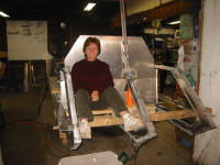
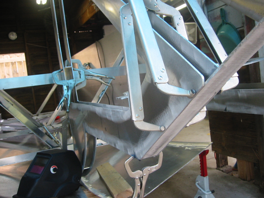
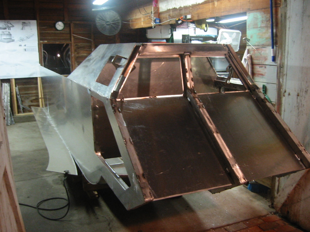
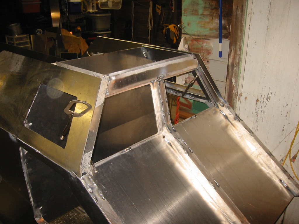
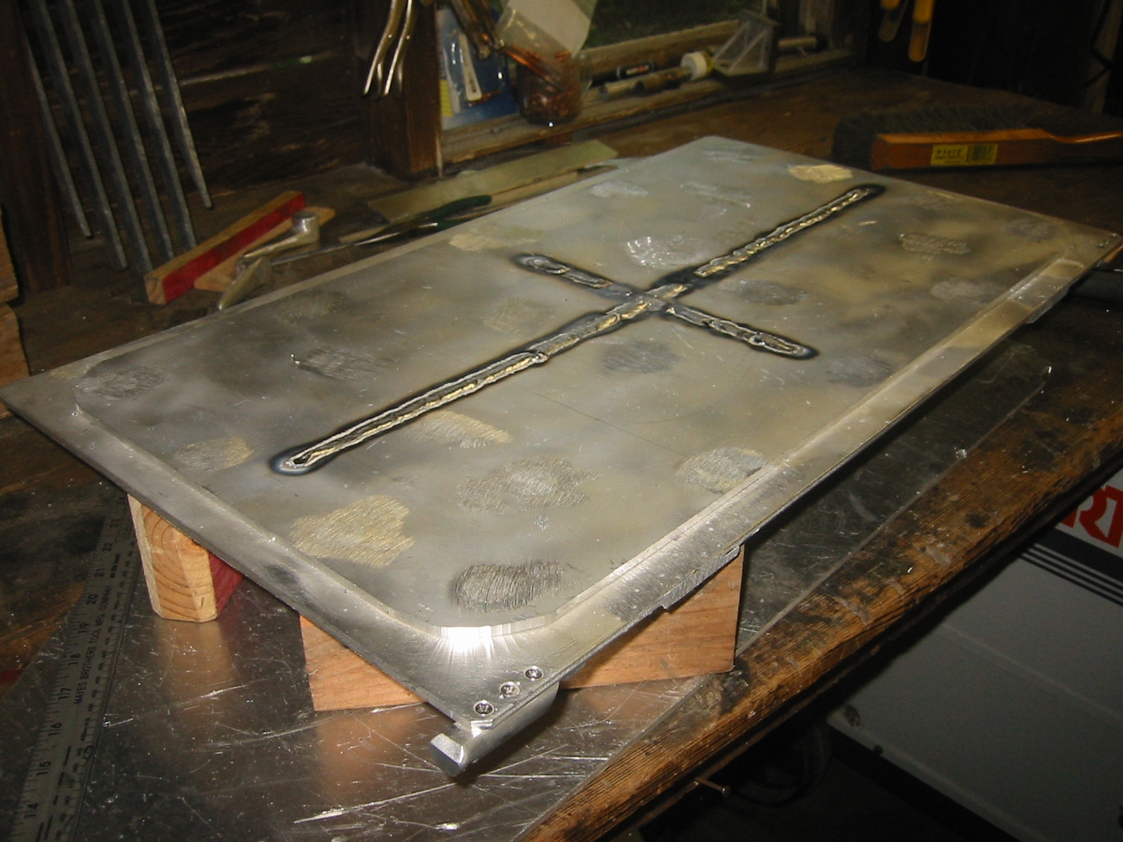
Cabin Assembly(1) The cabin bulk head is in. I have a pattern for this piece created from the CAD drawings, but from this point on the parts are subject to changes where the CAD drawings were not detailed, and where it was just impossible for me to figure out exactly how the parts would fit together, even when looking at a 3-D model. Perhaps it is because this is the first time that I built something with more that a 2-D drawing on paper. So the construction now is more like building a house; something I understand. The plans and patterns give direction but the detail in left to the builder. This will drive most engineer types nuts, but the carpenters of the world will feel right at home. (2) If you need to push something into place, there is nothing like some 4x4's and a 2 ton bottle jack. The cabin's rear bulk head has a bend so that it slopes back like a chair. Every cubic inch of air that can be squeezed out of the cabin is that much less lead ballast that has to be carried around. If you think this cabin looks small now, wait till its fully enclosed. (3) You can put a sharp bend in 3/16 inch aluminum with a break press or by cutting a groove where you want the bend. There is not much stress on this bend, so I cut a groove with 3 passes of the skill saw removing about half of the material. Even with that it took my wife and I jumping up and down on the piece to get the bend started, and the hydraulic bottle jack to finish it off. The neighbors got a kick out of watching two 40 something's bounce up and down in the driveway like kids on a bed, but it was also a great confidence booster to see just how strong this material is. (4) The welding on the outer frames caused them to bend inward about 3/8 of an inch, so bracing was required to force the frame back to where is was suppose to be. Then the cabin's upper side frames could be fit in place. Since the upper section meets the lower section at a 12 degree angle, the webbing between the upper frames is 1 1/2 inches as opposed to the webbing in the lower frames they rest on which is 1 5/8 inches. That difference and some grinding is enough so that the joint between the upper and lower sections is horizontal. This was done just to make to joint a little easier. (5) The upper cabin framing is in place, and the bracing has been removed. The header across the front windows is now supporting the center frame in its correct position so the bottle jack has also been removed. (6) One half inch flood and vent holes are drilled at the appropriate locations so that the inside of the frame will flood when submerged. This will help to decrease displacement and ballast weight requirements. December 15, 2004 and after a 4 week break, and closing in the shop with a few more tarps in order to keep the cold out, I'm back to work. (7) The cabin's bench seat is in after more bending on the lower hull, to form the bow. I sloped the seat forward just a bit so water will drain onto the hatch when the boat is trimmed. Since the bottom hatches will be the lowest points I am planning on drilling a small hole through the hatch and installing a spring loaded valve that can be opened to purge water from the floor of the cabin. The forward edge of the bench, the center and side frames, and a flat piece under the heel rest form the hatch opening. (8) The heel rest is made from an 1 1/2" pipe that was cut in half. An additional flat bar under the heel rest and turn up on edge (see photo) was latter removed as the heel rest does not require a stiffener and additional structural framing to protect from impacts would be provide by the lower hatch frame. (9) The bottom hatch frames are going together. They are constructed from 3/16, 1 1/2" 6061 T6 angle, and form 2 frames, one which fits inside the other. They will be held together with stainless steel screws and they will sandwich a 3/4 inch sheet of cast acrylic. The space between the frames is actually 1 inch in order to allow for the acrylic to be bedded in a 1/8 inch layer of silicone on each side. (10) The Boy", aka Carl, my son, was home from the Army for Christmas
Break so he got a taste of the grinding work that lays ahead.
Having done enough grinding that I know it's the part I truly
dislike, I plan to utilize him on between his Combat Medic training
and his likely deployment to Afghanistan this Summer. Acrylic View Ports
Deciding on 3/4 inch acrylic was not an easy task. The submerged
speed applies only a small force. If we hit 3 knots I'd be
surprised, but in a 6 ton sub in
a lake with 20 foot of visibility, I'd be nuts to want to go any
faster. The acrylic will be 3/4" but that is
intended to stop the submerged
log from coming through it. The
greatest normal force will be on the lower foot rest sections when
they hit a wave on the surface where we might be moving at 20 mph.
The foot rest are about 7 x 22 inches and I
don't remember what the impact
load was, but I looked like it would be sufficient. :) Since the
cabin is ambient the other big loading force is on the upper view
ports because the air trapped inside wants to get out. It' kind of
like an aquarium in reverse --
take an acrylic aquarium, empty out the water, turn it upside down,
put it in a room full of water,
and fill it with air. Hence I got my best information about sizing
the acrylic from aquarium
builders.
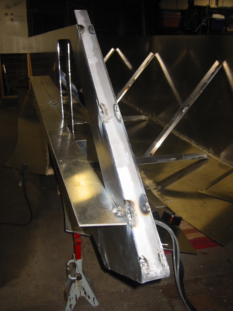
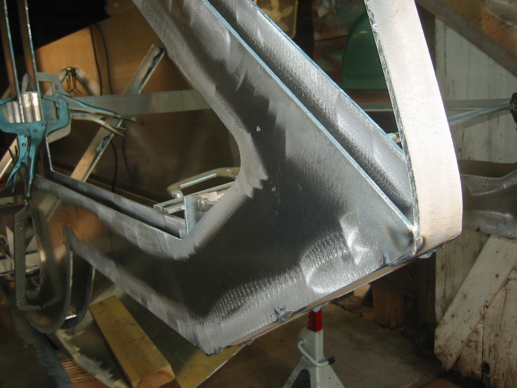
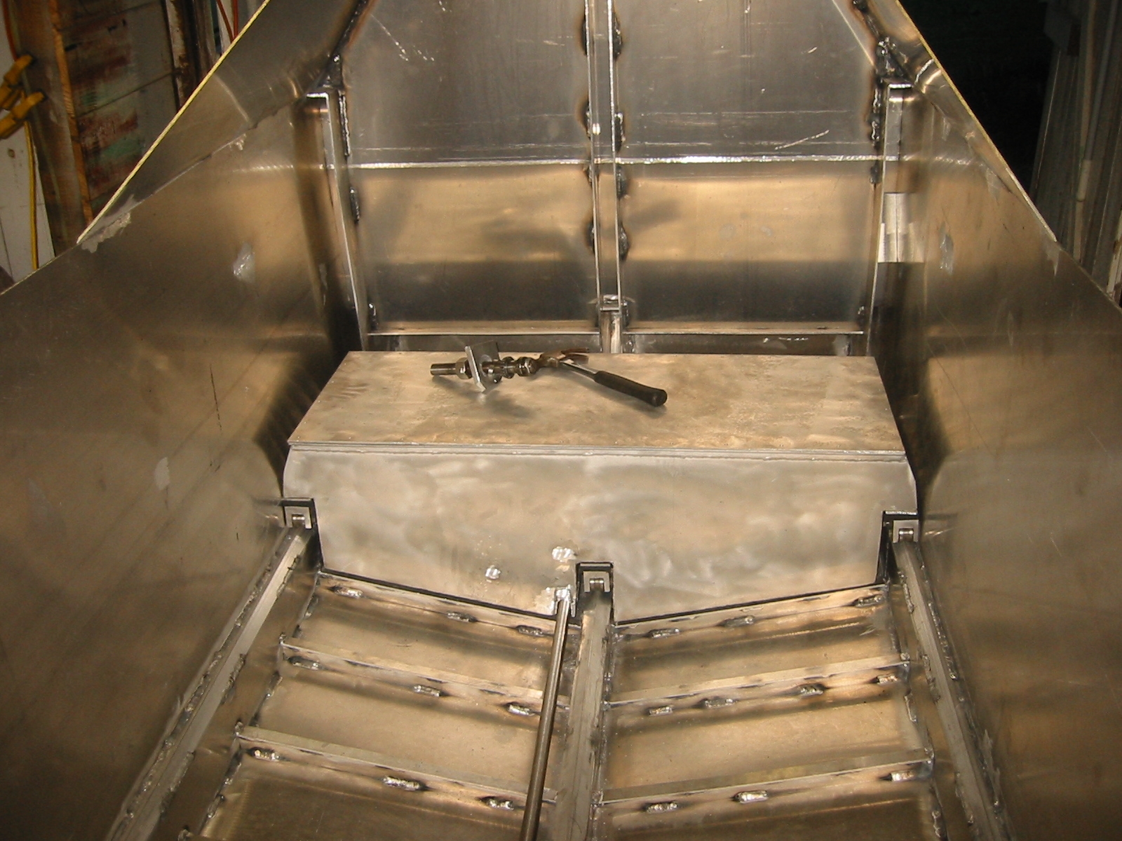
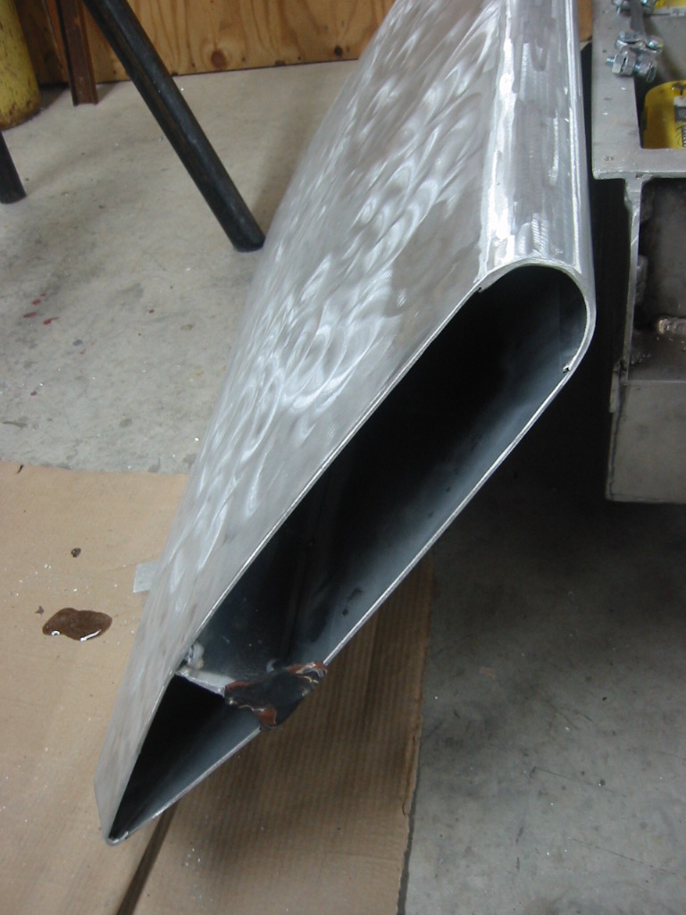
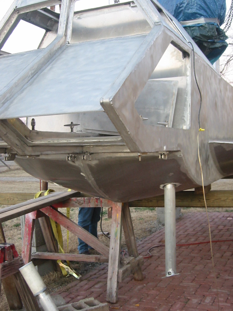
Lower Hull Extensions - Pontoons(1) I guess I'll call them pontoons for lack of a better term. Perhaps running boards is better? They are really extensions from the lower hull, and if I did the math right they will be partially awash when the boat sitting still in the water. They provide additional displacement to reduce the draft, additional surface area in order to help the boat plane, and serve as a swimming deck. They are not extended above the water line so that they do not needlessly increasing the boats cross section. Limiting the cross section will improve the top speed while submerged. (2) (3) The pontoon is only 12 inches wide so bending it up was not nearly as challenging as the bow. The plan was about 1/4 inch off on this piece between the bottom and the inside hull. A 3/16 inch piece of scrap was used to fill the gap and small stitch like welds that bridged the gap were added until they were about 1/2 inch apart and a continuous weld could laid down. (4) Inside welding was completed and then a 3/4 inch piece of angle was added in order to provide a temporary brace for the top. Once the top was in place the angle could be twisted from the rear and the tack welds broken. This ended up working just fine, but since the rear of the boat is only 10 inches from the back wall of my shop, I will have to wait before I can recover my angle. (5) (6) Having scrap aluminum laying around makes it easy to quickly knock together the perfect brace and pry bar for each special requirement. The top of the pontoon had to be pulled in against the side of the hull and then the side of the pontoon had to be pulled out to meet the edge of the top. The bottom outside edge was then ground smooth, in preparation for a continuous weld that will eventually cover the seam. If you don't mind a little danger you can reduce the grinding requirements by using your circular saw and router free-hand. I trimmed about 3/16 from the outside edge of the pontoon's bow and beveled the bottom edge of the entire pontoon. Before you do this, you should know that this is how people end up with 8.5 fingers.
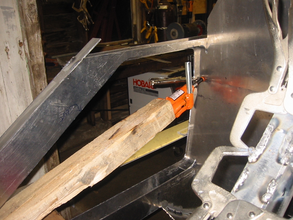
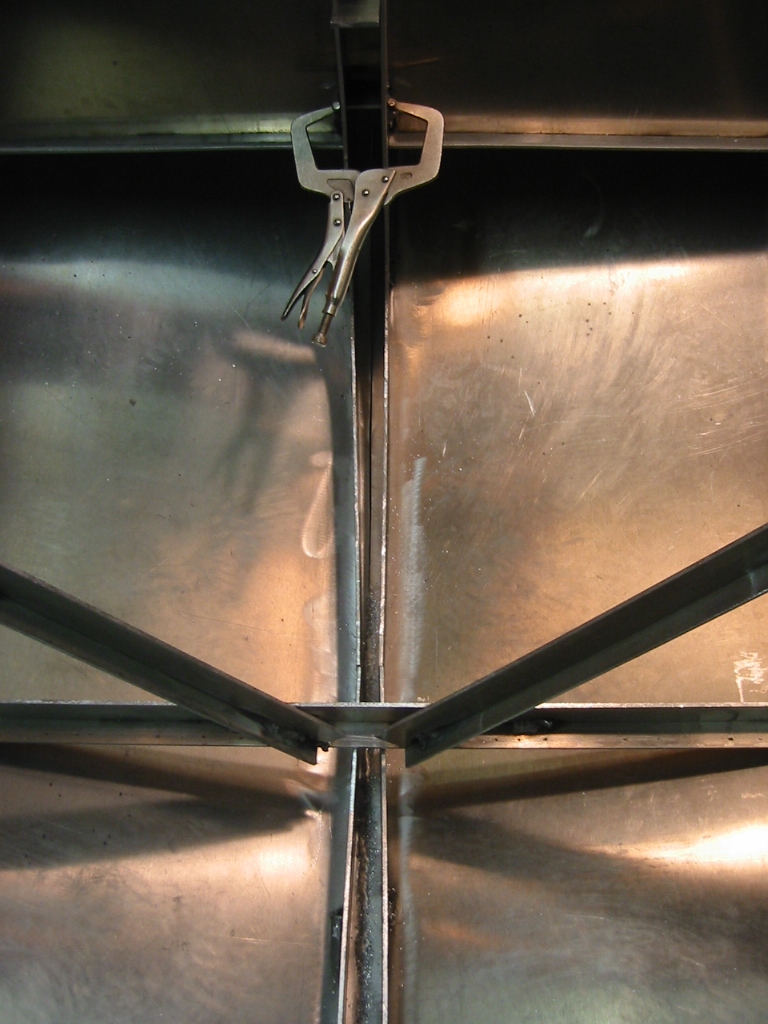
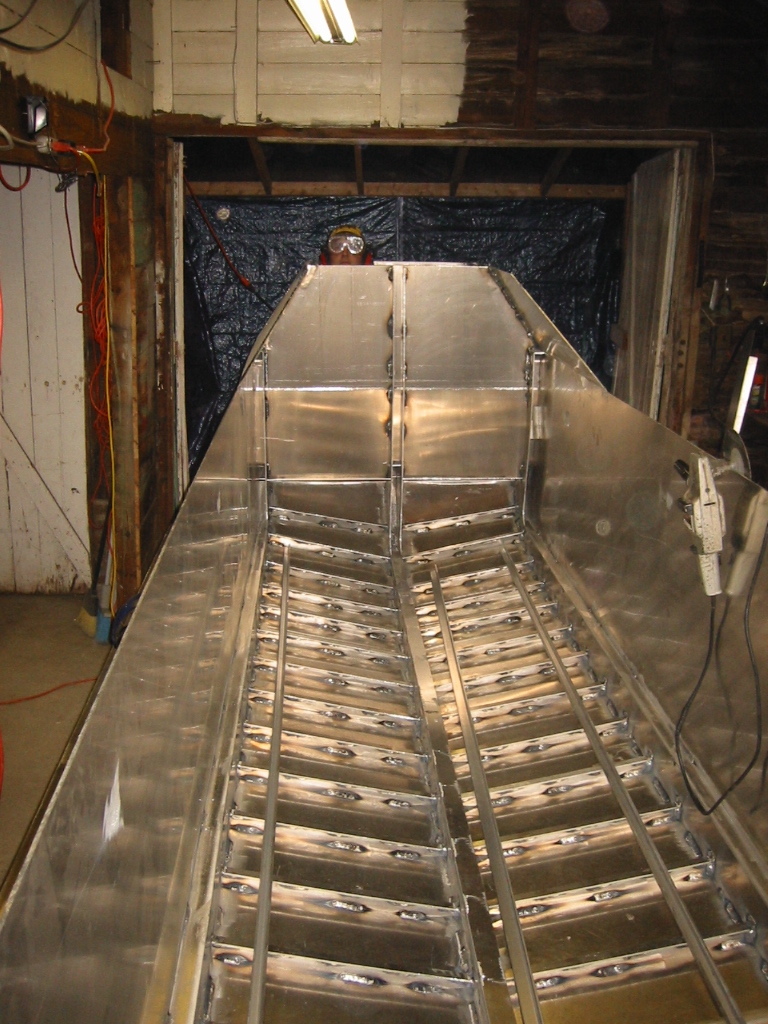
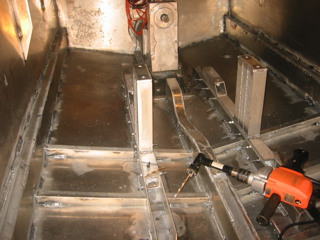
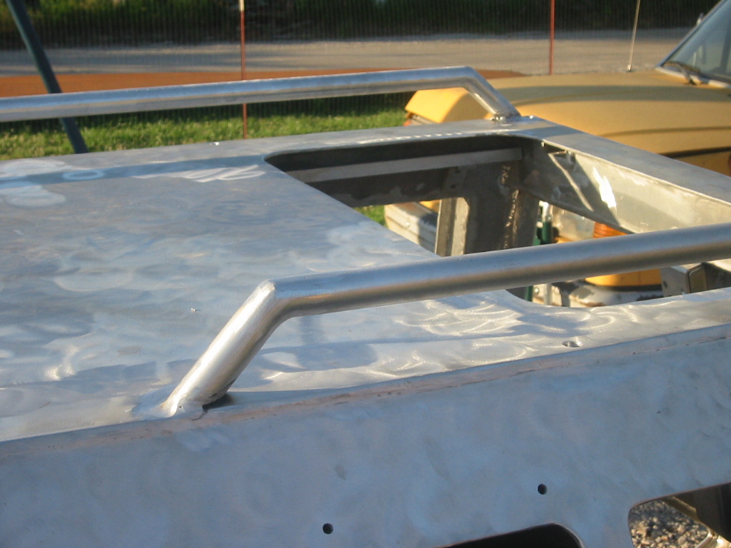
Framing the Main Section of the Hull(1) "For every action there is an equal and opposite reaction." In this case it pulling the hull up to form the bow, bowed the two center frames out of place. (2) A relief cut relieved the pressure but cutting frames once they are in place is a bit of a problem. The circular saw will cut about 2 1/2 inches, then a reciprocating saw can get all but about the last 1/2 inch and a couple of holes will weaken the remaining material and allow the saw kerfs to close up. Welding the joint back together will further pull the joint together, but be sure to place a temporary plate behind the butt joint in order to prevent the weld from burning through. (3) Thirty T-frames on 10 inch centers have now been
welded in place starting from the bow back to where the engine
mounts should begin. Each frame is 1.5 inches tall, with a 1 inch
tee from the same 3/16 sheet used throughout boat. Rat holes were
precut in each frame to allow for drainage down the keel. A
good trick here is to cut yourself a couple of sticks that space the
frames properly and support them at 90 degrees to the bottom. Each
frame was intentionally cut a 1/16 or so long and ground to its
final length for a snug fit.
|
|||||||||||||||||||||||||||||||||||||||||||||||||||||||||||||||||||||||||||||||||||||||||||||||||||||||||||||||||||||||||||||||||||||||||||||||||||||||||||||||||||||||||||||||||||||||||||||||||||||||||||||||||||||||||||||||||||||||||||||||||||||||||||||||||||||||||||||||


|


Once submerged the seal will further compress and opening the hatch while submerged will be impossible unless the cabin is completely flooded. Flooding the cabin will only be done in an emergency, and unless the sub is already on the bottom flooding the cabin will cause a significant lost the buoyancy and instigate a rapid decent to the bottom so getting out quick will be important and I don't want to be fooling around with more than one leaver. If the situation has deteriorated to this point is also implies that there is something preventing you from exiting the cabin through either of the two bottom hatches, like the ocean floor, lake bottom, or a net. The bottom hatches are the preferred emergency exit path since they can be opened while there is still air in the cabin and before the sub is rocketing downward.
Oops ...After all the calculations and Carl doing a beautiful job turning the parts for the top hatch we played around with fitting it into place and learned that I did not account for the outside handle when I decided that the hatch would slide inside the hull and rest against the back wall of the cabin. With the outside handle the hatch would be 2 1/2 inches from the back wall and way too cramped. (3) After debating creating a recess in the back wall to accept the handle, we finally decided to ditch the handle altogether. The only reason for it is to allow for rescue access if the occupants are unable to open it. It's not a real loss, the bottom hatches can still be opened from the outside which is a safer entry route anyway, and its one less thing to leak air or snag an entanglement. So, now we have the 3rd and hopefully last version of the top hatch.
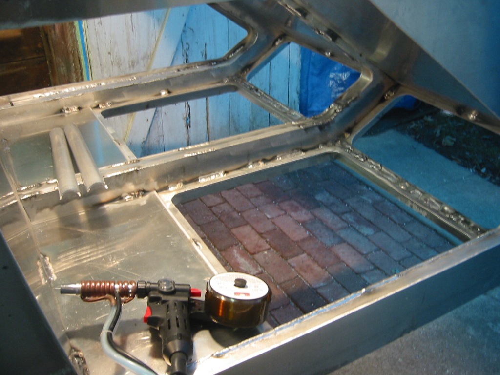
(4) The top hatch is now starting to come together. Carl machined the spindle parts and the center hub along with inside bracing and guide for the dogs are in place. The inside bracing was welded the the hatch thought a set of 5/8 inch holes drilled through each brace and the outside sheet was done the same way. It is not recommended in the metal boat building books to weld sheet material together like this because of the problems caused when oxidation starts to form between the sheets, so I guess I'll see how bad it gets because I have to have a thin hatch in order to accommodate it when it comes inside the cabin. I thought that I might be able to get by with only adding reinforcement to the inside but that was not to be the case. Even carefully allowing the parts to cool between each weld did not prevent the hatch from bowing inward about 1/4 of an inch. (6) The addition of a sheet on the outside does have the added advantage of filling the recess so that the top of the hatch is now flush with the top of the sub. (5) The top sheet was welded on with the same technique as the internal braces, however the welds were not enough to correct the inward bow, so I made a couple of 1/8 inch deep saw cuts across the sheet and welded them closed. That did the trick! As the welds cooled they drew the sides of the cut closer together and pulled the bow out of the hatch. In fact it was a bit too much but a couple 1 1/2 inch welds (without cutting a notch) on the other side corrected it back.
(5) (7) (8) The hatch has two notched pins that will slide on rails in order to allow the hatch to slid back over our head and hang against the rear cabin wall. I since have removed the notches and only have the pins in order to reduce the binding. Since the hatch only hangs on its' rails by two points there is nothing to keep it aliened as it is moved.
RTV for a Hatch Gasket
|
|||||||||


The two part RTV that is intended for making molds, and which I sometimes use for potting does not make a good gasket because it does not stick well to metal. The RTV I am testing here, is the stuff you get at the auto parts store. It comes in small tubes as well as calking gun size tubes which sell for around $15.
Most of the time you just put some of this between to parts and bolt them together. But my neighbor Travis recommended this method for making a reusable RTV gasket. Reusable because the hatch is repeatedly opened and closed. You use wax paper between the two parts so the RTV only sticks to one side. (1) I used a spray adhesive to help tack the wax paper in place, the laid down a bead of RTV. (2) Then
|
|
genially pressed the parts together. (3) After 30 minutes the parts can be separated allowing the RTV to cure faster. Do not try to removed the wax paper. (4) Let the RTV dry 24 hours first, and then the wax paper will peal off without lifting the gasket. (6) Finally, trim away the excess RTV.
(7) RTV is a soft material and it does not take much abrasion to peel up the edge. So I roughened the aluminum up with a rasp and made another test piece. (8) This did help but it also helped to trim the gasket back from the edge of the aluminum and trim it at an angle. Both make it more difficult to peel up. When it did peel away from the aluminum it stretched and did not easily tear and it would fall back in place where it would still be usable.
|


Surface Finishing
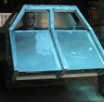
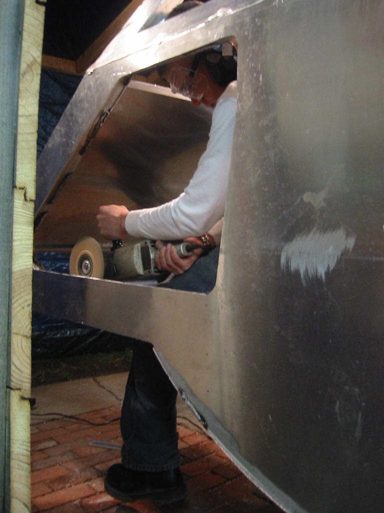
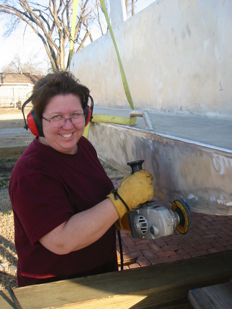
(1) Carl is modeling the cabin which now has the bottom hatches installed. We have also decided on finishing the surface of the boat by simply brushing the surface with a cup brush and Randi my other assistant has volunteered for the job. Running a 5 pound angle grinder will help build that upper body strength she wants. The small patch on the front deck is a sample of the brushed look. It will also be a great way of hiding small scratches.
The inside of the cabin will be painted mat black order to reduce glare and also to insure an air tight seal on all of the welds.
(2) Randi, my other assistant, volunteered for the job for the job of brushing the external surfaces of the boat with a th a cup brush and a 5 pound angle grinder. That will help build that upper body strength she wants too.
|

Aft End Hull Work
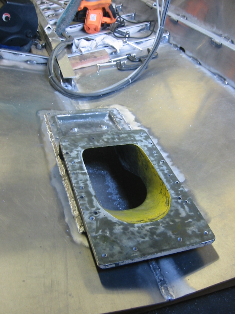
It's May, 2005 and it has been a while since I was in the back of the boat. (1) I am installing the intake for the jet pump. It feels good to be back working on the hull, even though cutting a hole in the bottom is not comforting.
(2) (3) After test fitting the jet pump on the intake I welded in the intake. I could have bolted the intake in place but I figure I'll have no need to remove it and the welds should help it take the additional forces that will be applied through the gear box that is bolted onto the pump.
As mentioned before the details of how each item will be completed was not part of the original plans. Doing so would have restricted the design and not allowed for me to apply knowledge that I gain along the way, so in keeping with the organic design process I marked out where the gear box and engine would go and the stood in the back of the boat and decided the best place to put frames for the rear deck that would provide convenient access to the engine and ballast sled.
(4) The rear cabin deck, frames and transom were all
installed in one day with Carl's help. It's nice to have him for a
couple of days before he leaves for Iraq. I took advantage of the
muscle put on him courtesy of the US Army to get the boat framed up
and out onto the yard where I could completed the bottom welding and
get it on it's trailer.
|


Roll Out
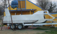
(1) The boat finally meets the light of day. (2) I welded a steel dolly with 4, 10 inch tires and leveraged the boat out of it's plywood construction cradle and onto the dolly. It was then easy to roll it out of the shop an out onto the lawn.
There was over 2000 pounds of aluminum purchased for the boat, but it's hard to say what actually ended up in the hull. I'd venture to guess its about 1000 pounds. (2) Once on the lawn we levered it up an pulled the dolly out and then rolled it up onto its side and we blocked it there so the bottom could get it's final welding.
Here is a lesson: If you want to make a small shop look huge, just remove the 20 foot boat! I had planned on rolling the boat back into the shop on it trailer, but that will not happen because the trailer it's too wide for either set of doors. So now I am planning on building a temporary shelter to house the boat in the drive way just outside the shop.
With Carl off to Iraq, rolling the hull over onto
it's other side just got a lot harder and slower. I improvised a
crane out of the 4x4's that were once the pallet the aluminum was
delivered on, Kay bolted on a worm gear winch. I welded on a couple
of hand holds that served as lifting points onto the sides. Even
then we had to use an engine lift to help raise it, but it worked
fine for lowing it back down.
|
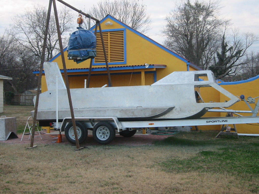
Trailer Modifications
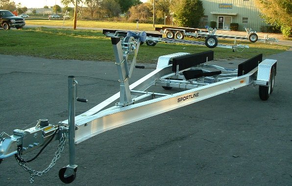
I considered building my own trailer but after looking around a little I soon found that I could buy a new trailer cheaper than I could build one from new parts. (1) I got a Loadmaster Sportline designed to haul 6000 pounds from Pirate Marine out of Ohio, and with delivery the cost was less than $3000. A used trailer would have saved money but finding a used aluminum trailer in Oklahoma is almost impossible.
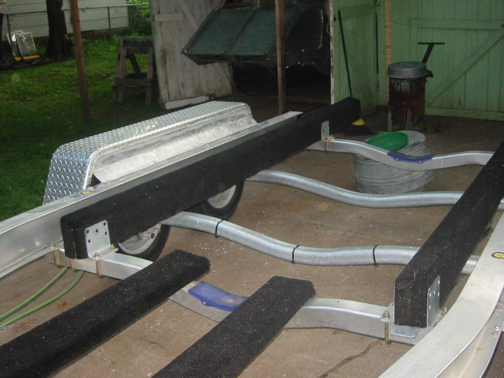
I lowered the trailer bunks about 7 inches by cutting down the bunks and cutting down their brackets. The idea is to get the boat to sit as low as possible on the trailer so that it floats off without having to back so far down the boat ramp that there is no more boat ramp. The boat will actually fit between the fenders of the trailer with less than an inch on each side, but I will reinforce the fenders add add a bumper rail if needed. They will make nice steps once reinforced too. Since the side will be covered by the fenders there is some finish welding to be completed before I drag the boat from its dolly and onto the trailer.
|
|
(2) Randi helped me reinforce the fenders today. They are now enclosed and each have 5 additional bolts holding them to the main I beam. This makes the sturdy enough to stand on and protects the hull from objects kicked up into the wheel wells.
(3) After completing the finish welding the sub was levered and winched from its dolly and onto the trailer.
We are enjoying some beautiful weather for this 2005 Memorial Day, and I hope that next year about this time we will have the sub in the water. (Note: It is now 2008, Memorial Day and we now plan to be in the water by August, however we have built and house, healed Carl from wounds sustained in Iraq, married the kids, and I am now a grand dad, so hence the delay.)
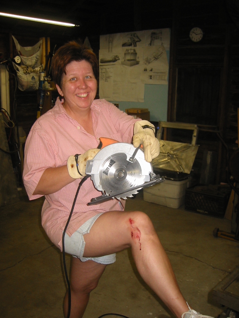
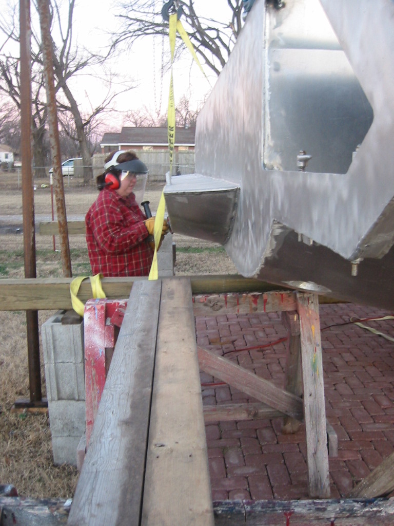
With Carl gone I have been forced to recruit more labor from the family labor pool which means Randi and Kay. Some days it has to be viewed as a long term investment, because it takes a lot of time when your help is starting from almost zero experience but we are making fast progress up the learning curve. We did experience one training accident. Kay went and found a sharp corner on the trailer with her leg but she is a real trooper. I could not ask for a better pair of helpers or a better wife and daughter.
|
A-Frame
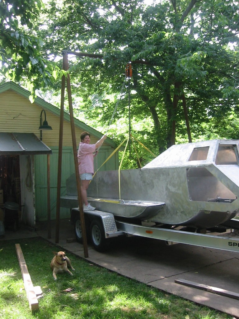
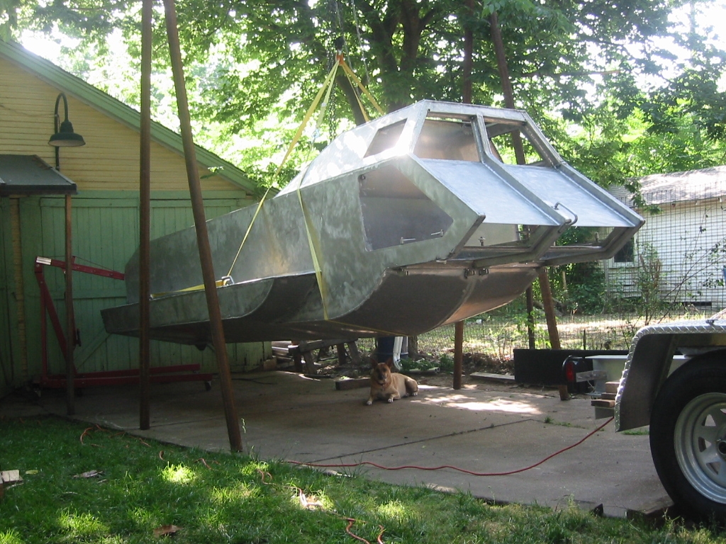
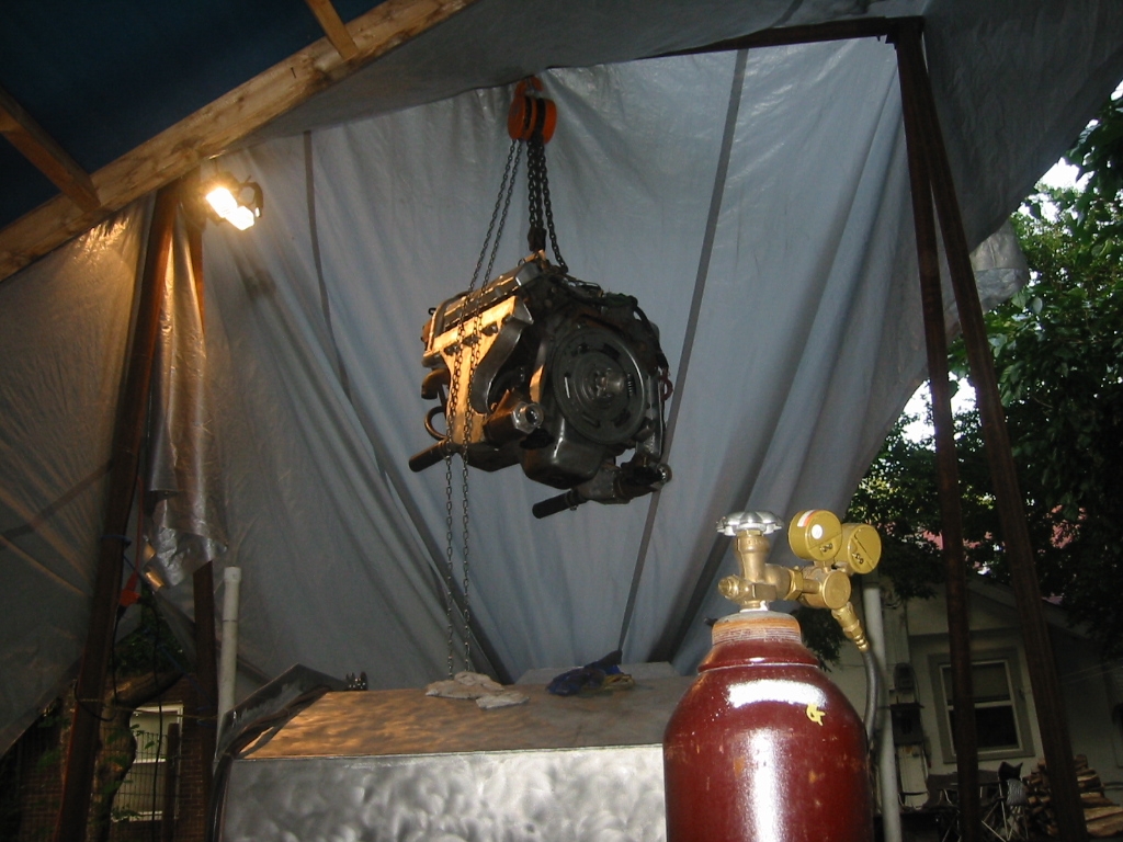
I have an engine lift but that just wont lift the engine high enough to clear the side of the boat when it's sitting on the trailer so I built an A-frame from 1/4 inch thick, 2 1/2 inch ID steel pipe. The legs are 13 feet long and the cross piece is 8 feet long. To hold it together at the corners I used 2 1/2 inch OD pipe. Each corner is built from 3, 16 inch pieces welded together with angle for reinforcement. The legs and cross piece just slip over the corner bracket and only 1 bolt is used the secure the cross piece so it does not slide out. Each leg must weigh 60 pounds, so standing the thing up is a bit of a task, but it needs no additional bracing. The steel cost $75 from the scrap yard and Harbor Freight had their 3 Ton chain hoist on sell for $65 dollars.
For a test run we hoisted the boat off the trailer so we could alien and secure the bunks. We used the engine lift on the transom just to keep the boat balanced, but the hoist and A frame worked great. I could not see any bow in the cross member. We have since made a habit of lifting the sub with the engine which is over 2000 lbs. This is best done using two host so that the load is closer to the supports and not in the center.
Engine Installation and Other Aft End Work.
I worked on the sub two days this weekend but can't really show much for it. I had planed on getting the engine mounts made but one distraction led to another and I only managed to get the brackets for the engine partially made. Seems like everything always takes more time than I ever expect it to. It was a pleasant weekend, none the less. We did get a lot of the new hull parts brushed and I even got a couple of hours work out of Kay.
|
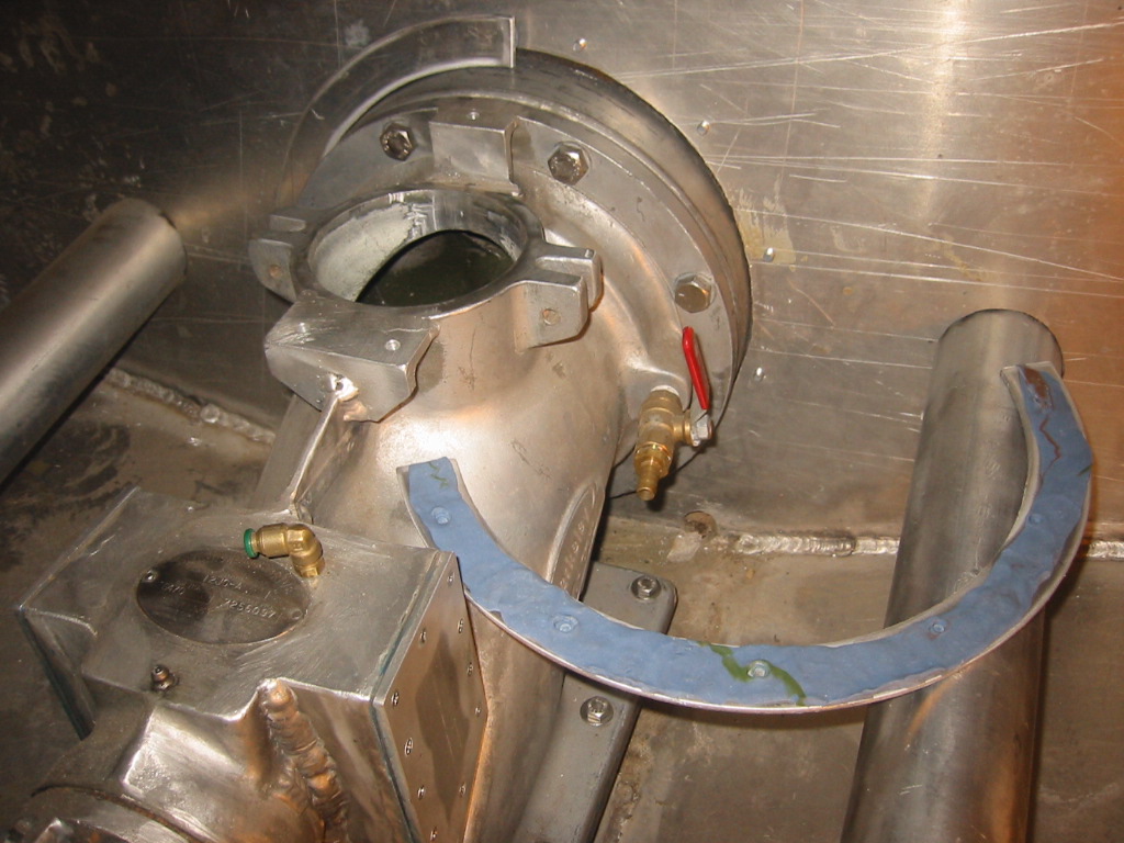
(1) We can finally get a good photo of the transom. The jet pump came with a flange but it's to bulky are requires the control cables to be routed where they interfere with our custom clean out port valve. So instead we are just using a coupled of flanges that compress a neoprene gasket against the pump.
(2) Openings for air tanks were cut through the side hull extensions. A 300 cubic foot air cylinder will be housed in each side to provide air when we are not using the hookah compressor on the surface. The valves for these tanks will be accessed hatch openings to the inside of the hull. This will also allow the side extensions to flood and drain.
(3) Kay fitted hatch covers for the air tank openings. The hatch plate is held down with 1/4 inch bolts that are tapped into the hull. A neoprene gasket will be used to seal the hatch.
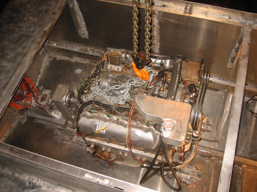
(4) The engine was suspended from the A-Frame so it could be lowered into position and measurements taken for building the engine mounts. (5) The engine mounts made from 2 inch square tubing and they are bolted into longitudinals on the hull bottom. The photo also shows the dip in the center framing that accommodates the standard oil pan on the engine. The center frame will be a tunnel through the engine compartment that will allow bilge water to drain from the front.
(6) The sitting on the mounts. Next comes the lower half of the engine compartment that will keep the engine dry.
More Aft End Work
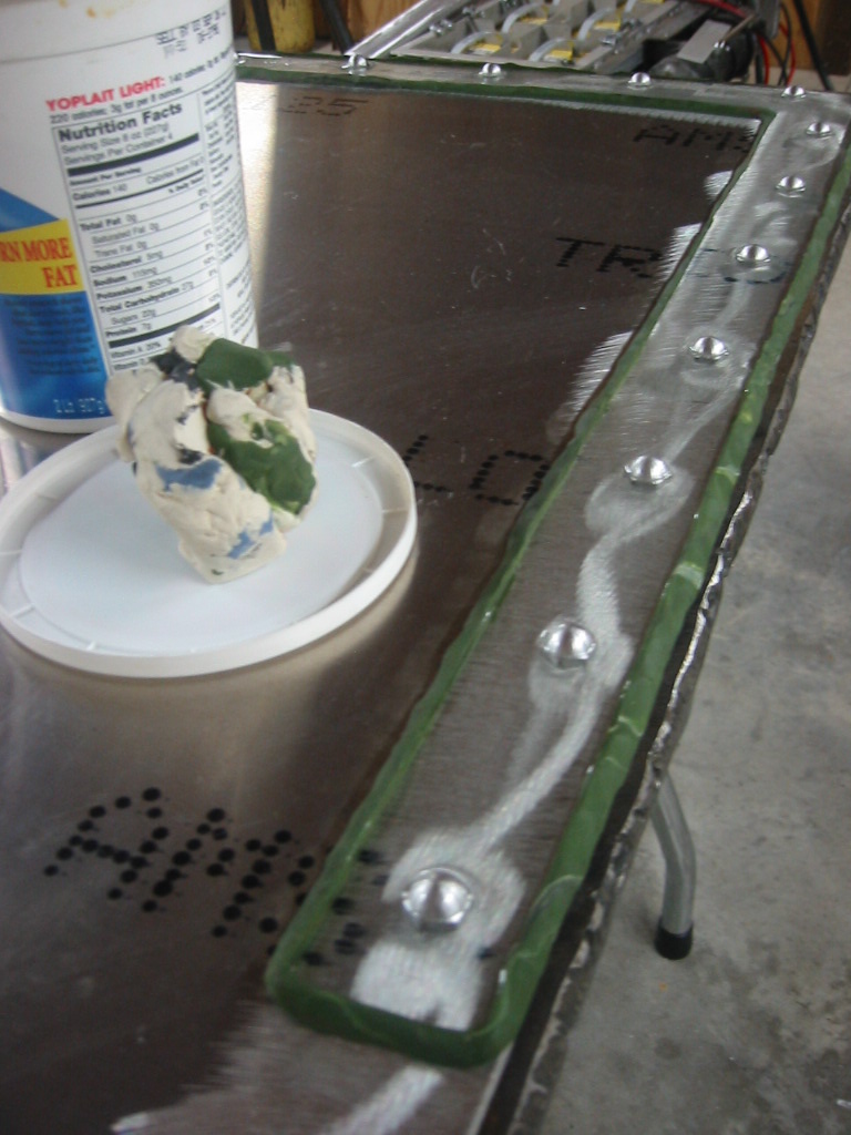
(1) There are bolts sticking through the transom that are holding on the outside flange around the jet pump, and those same bolt need to hold the flange on the inside. To mark where those holes need to go on the inside I coated the flange with a thin layer of molding clay, then positioned it and pressed it against the bolts. I have also used the trick of dabbing a little grease or calk onto the end of the bolt, but I think the clay works much nicer.
(2) The drain hole in the transom can not be in the bottom of the V because of the jet pump so water and trash kept collecting there to form a little swamp. The problem was easily solved with epoxy mixed with an equal measure of talc. The boat was trimmed and then the mixture poured in to the space previously occupied by the swamp water.
|


Having gone through a dozen of those 5 Minute Epoxy syringes I decided I should indulge my love for the stuff so I purchased a 1 1/2 gallon kit of the stuff from www.jgreer.com and now I have placed my second order. Adding talc is a great way to bulk up the epoxy and get more for your money. Wood flower, aka: fine saw dust also works. If your belt sander has a collection bag then you already have a ready source for wood flower.
The forward and aft trim tanks are formed by simply closing off the top section of the front and aft end of the hull. These partitions must be removable so that the machinery behind them can be accessed. They also have to be air tight. The welded seams have been sealed with a coat of epoxy to seal any pin holes. And the partitions will have a neoprene gasket against the frames and will be bolted in with 1/4 inch acorn nuts on the back side of the panel to prevent leaks.
(3) Welding aluminum nuts to a 1/8 inch sheet is a skill beyond my ability so the nuts are glued to the back side of the partitions with epoxy. Modeling clay is again put to use to make a dike to retain the epoxy. The surface of the aluminum was first cleaned with acetone and then roughened with a sanding disk to give the epoxy a better surface to grab onto. The acorn nuts are temporarily held in place with bolts from the opposite side. There may be a problem with expansion breaking the epoxy off but that will remain to be seen. I smacked the nut on a test piece with a hammer and all it did was crack the epoxy so it should be more that sufficient.
(4) (5) While on the topic of epoxy I have also used it to
seal up a joint on the inside of the tail/snorkel. The tail fin is
larger than required for just providing air to the engine so it is
partitioned so that the back portion will free flood separate for
the actual air intake path.
The partition was welded to one side of the snorkel before the
halves were put together but the other side of the partition was
only spot welded in place through holes drilled in outside sheet.
In hind site it would have been best to weld flat strip onto the
partition to make it into a T so that the it would have exposed a
solid plate through the hole instead of just the 3/16 inch edge.
So, as for the epoxy, I just poured some mix down the un-welded seam and when it look like it was sealed up I added a little clay dike on each end and poured another mix into the joint to make sure it was good and sealed.
(6) I have I have also added a couple of view ports on the rear deck that will allow inspection of the rear trim tank. Once the partition for the trim tank is added, this will be an easy way check the equipment inside. The view ports each measure about 5 by 7 inches, and will have a 1/4 piece of acrylic bolted on from the inside with a 1/4 neoprene gasket. The 1/4 inch bolts are treaded to the 3/16 inch hull sheet and were wrapped with Teflon tape to seal them from leaking air from the trim tank.
(7) (8) The weather is warming up have we are back to working on the hull in that one hour between getting home from work and sunset. Kay has taken on running the grinder in order to make my welds look their best. The external welds are just smoothed out if the seam is only welded on one side, and they are finished flush if the seam was welded on both sides
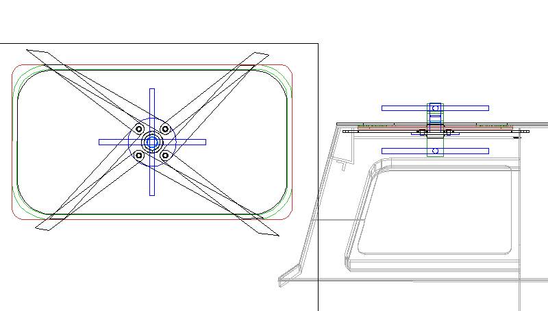
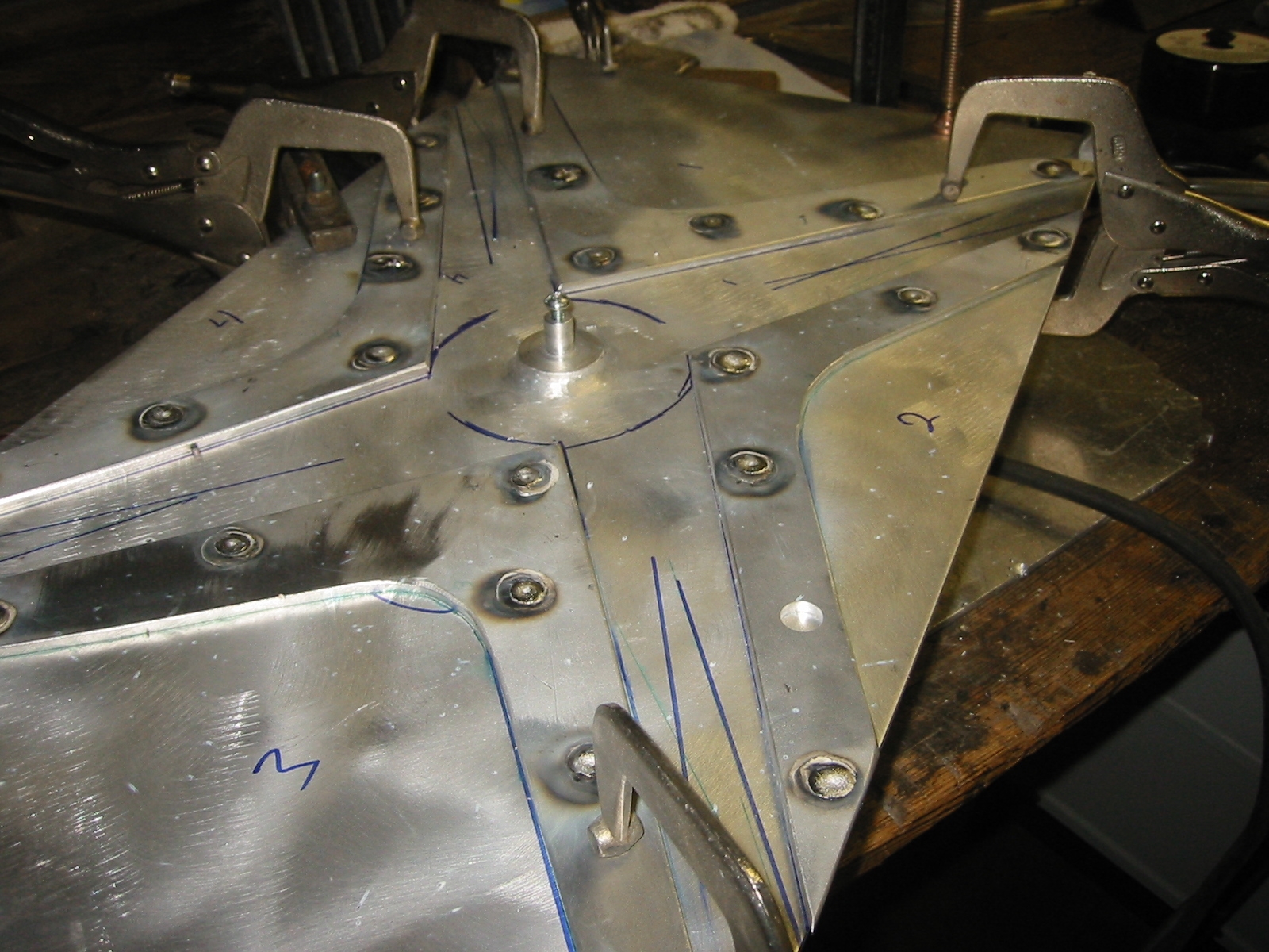
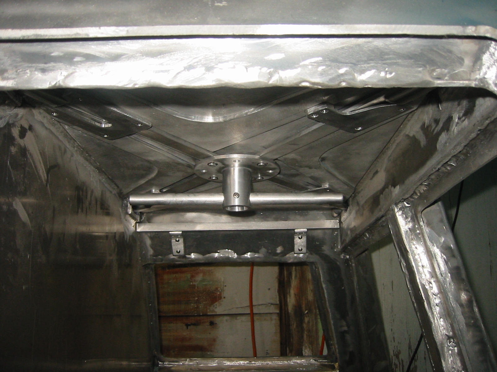
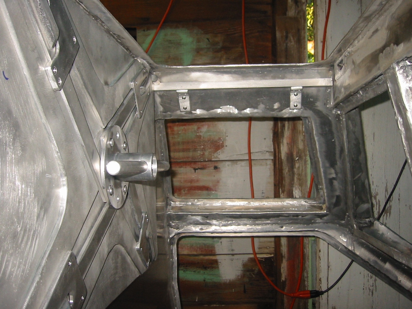
(9) The support legs or landing gear are driven by electric linier actuators. The details of their construction can be found on the Landing Gear page.
The landing gear will support the hull only when it is underwater. They allow the hull to come to rest on the bottom while maintaining sufficient clearance for the lower hatches to be opened.
(10) More hand holds go in as a part of the push-pull cable system that is part of the Emergency Surface System. These will also make it a lot safer to ride on the surface while sitting on the cabin top.
(11) (12) The air supply system is now in place and that included an air supply port on the back side of the forward trim tank. This port allows surface supplied air from a hookah system to be connected to the sub so that air from the high pressure system is not required. It also provides two ports for air lines with scuba regulators that allow for the crew to exit the sub while submerged.
View Ports
|
|
Finally ready to start thinking about installing the acrylic view ports. I've been worried about suitable mechanical fasteners but the boating industry secures their view ports in off-shore boats with glue, and the mechanical fasteners are minor if they are used at all. Life-Seal is a popular choice, but it is made specifically for fiberglass. Sikaflex is another popular choice, their site is www.sikaindustry.com. It creates a bond so strong that destroying the acrylic is almost a given if you want to remove the view port.
Sikaflex is sold for marine as well as construction, but with different names. The marine stuff is Sikaflex 295UV for the adhesive and Sika Cleaner 226 and SikaPrimer 209 for cleaning and priming the metal and acrylic surfaces. Sikaflex 295UV datasheet list the tensile strength at a whopping 450 psi. You can buy these from: www.jamestowndistributors.com or Merritt Supply www.merrittsupply.com, but check eBay too. Sikaflex 295UV is $13.29 a tube, SikaPrimer 209 is $49.36 and Sika Cleaner 226 is $12.37. There will likely be a hazards material fee.
You may be able to find "Sikaflex Constructions Sealant" and "Sikaflex 260 Primer" from a building supply and it is virtually the same stuff.
Steps:
Masking tape off the edge of the acrylic.
Lightly sand the exposed edge with wet/dry 320-400 grit sandpaper.
Clean frame and acrylic with Sika Cleaner
226 or acetone and wait 10 minutes.
Paint on a thin coat of SikaPrimer to the frame, the bonding surface
of the acrylic and the edges of the acrylic and wait 30 minutes.
Using the supplied V-Cut nozzle, apply a generous bead of Sikaflex
adhesive to the bond surface 1/4 inch away from the edge.
Apply 3/16 inch thick, soft rubber or plastic spacers every 10-12
inches next to the bead.
Set the acrylic in place and gently firmly press against the
spacers.
Clean up any squeeze out with mineral spirits.
Tool the Sikaflex smooth with a plastic spatula.
Once Sikaflex has firmed up, backfill the edge gap with additional
Sikaflex adhesive.
Remove masking tape from acrylic once Sikaflex has setup..
The acrylic came from a local supplier. A 4' x 8' x 3/4" clear cast acrylic sheet was $417.79 including tax.
Resources
Materials
www.epoxyproducts.com Epoxy Paint CM 15 with long potlife and lots
of flex for sealing pin holes while darkening the cabin. $65/gal.
www.jgreer.com Epoxy and RTV
Acrylic - Plastic Fabricators, Tulsa. 4' x 8' x 3/4" - $390 -- Ask
for Becky
Acrylic - Odd sizes: Check with Arrow Shield, Dallas 713-462-8021