|
|
||||||||||||||||||||||||
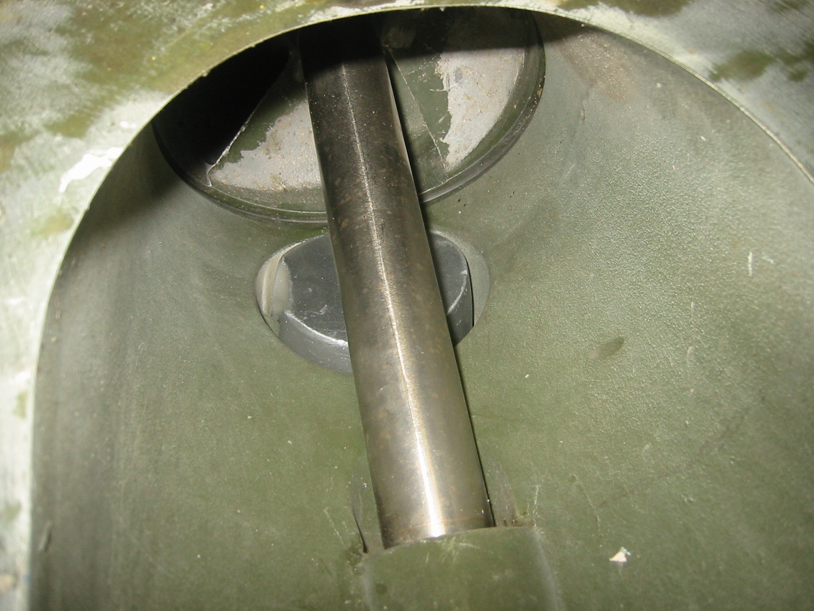
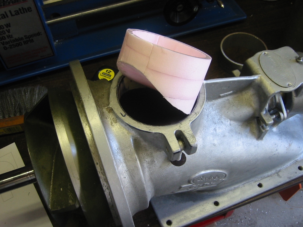
Jet Pump Cleanout Port ValveA typical jet pump will move about 5,000 gallons a minute. So even if it can still draw water through the intake grate, it should draw enough out from inside the hull to dry us out in 5 to 10 minutes. (1) I was a bit surprised how poorly the stock cleanout port plug fit the cleanout port opening. There was a 3/4 inch gap around most of plug and the opening of the port. I'd think that the jet boat racing performance concerned group would want a better fit in order to reduce turbulence and drag in the flow stream.
(3) The valve is a square box that bolts in place above the cleanout port. A new cleanout port will fit into the pump and then have a square top that can slide up into the square box above. (4) My first attempt was to use a windshield wiper motor to open and close the valve. Windshield wiper motors only cost about $20 and they are reversible, easy to waterproof, 12 volt, built for continuous operation, they have a worm gear reduction to about 80 rpm and they have build in and position switches. Someday I will find a good use for one of these but operating a valve was not it.
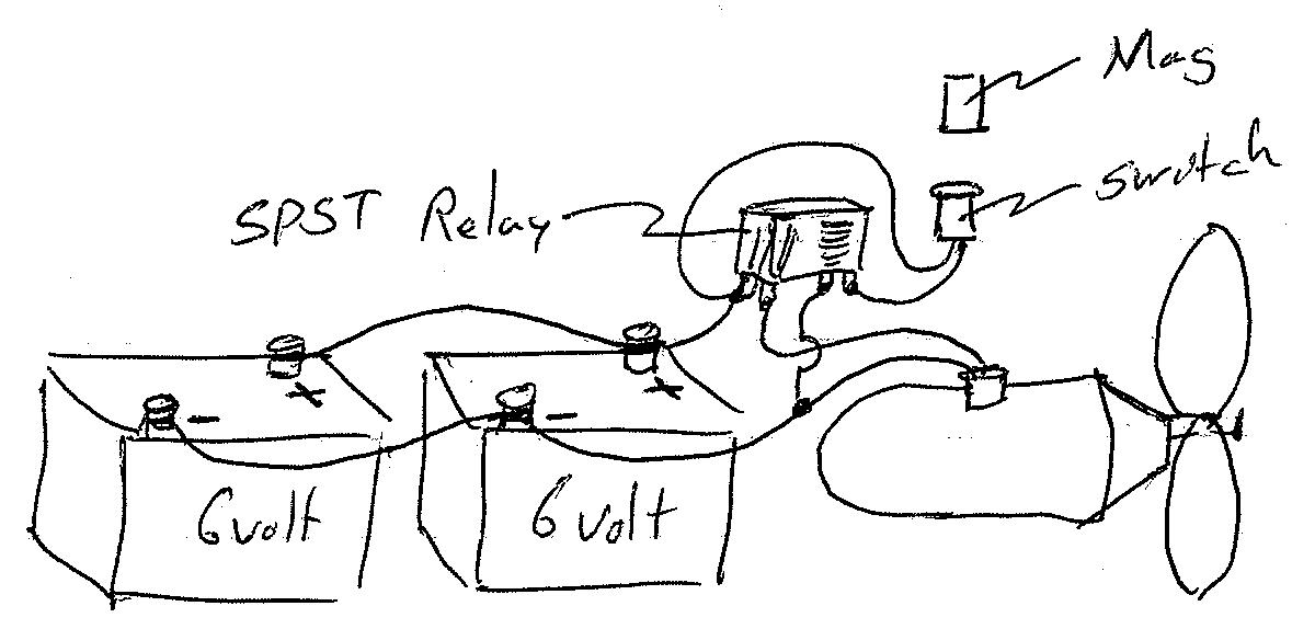
There was an internal switch in my wiper motor that I modified so that it is closed for about 170 degrees of each revolution. (5) Then I designed a relay control that would allow me to press a button, either open or close and that would start the motor running in either forward or reverse. A second, and smaller relay would then use the internal switch to maintain current to the main direction relay until the internal switch opened. The idea was that the rotation would stop at after just half a turn. I works in theory anyway. There a lot of bounce between the relays, but the main problem is that the motor rotation which is about 80 rpm is too fast to stop where it should. It would not do that under load and I could add a physical stop, but the bouncing relays and it is just too unpredictable How about reed switches? Attach a magnet to the arm and let the arm rotate 180 degrees until it hits a physical stop. At each stop a reed switch is opened by the magnet and that powers down the motor for that direction of rotation. The reed switch at the other stop would then be closed, so when the toggle switch is flipped back to the other direction, the motor would return to it previous location. And reed switches are already sealed so they are the perfect water proof switch. ...time to go shopping. Ok; well, the problem is reed switches are "normally open" switches and I need "normally closed". They say that magnetic switches for alarms are normally closed, but they mean when the magnet is in contact with the switch. There are some "normally closed reed switches, but they are rare and hard to find. Another problem is that most reed switches are only designed for 1 amp or less and windshield wiper motors pull about 4 amps under load. These magnetic switches will make great limit switches for small loads but they will have to be rigged so that the magnet is moved away from the switch or they will have to work in concert with relays. (6) As a side note, a magnetic switch and a SPST Relay would make a very simple switch for a scuba tow. There would be no need for any switch outside of the hull. Only a magnet would be needed to turn the thruster on and off.
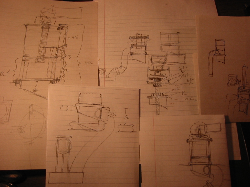
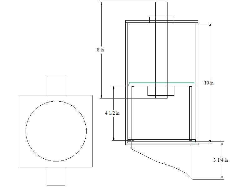
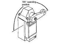
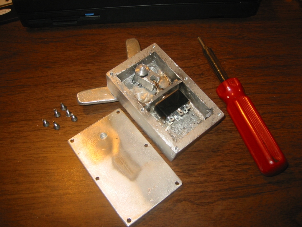
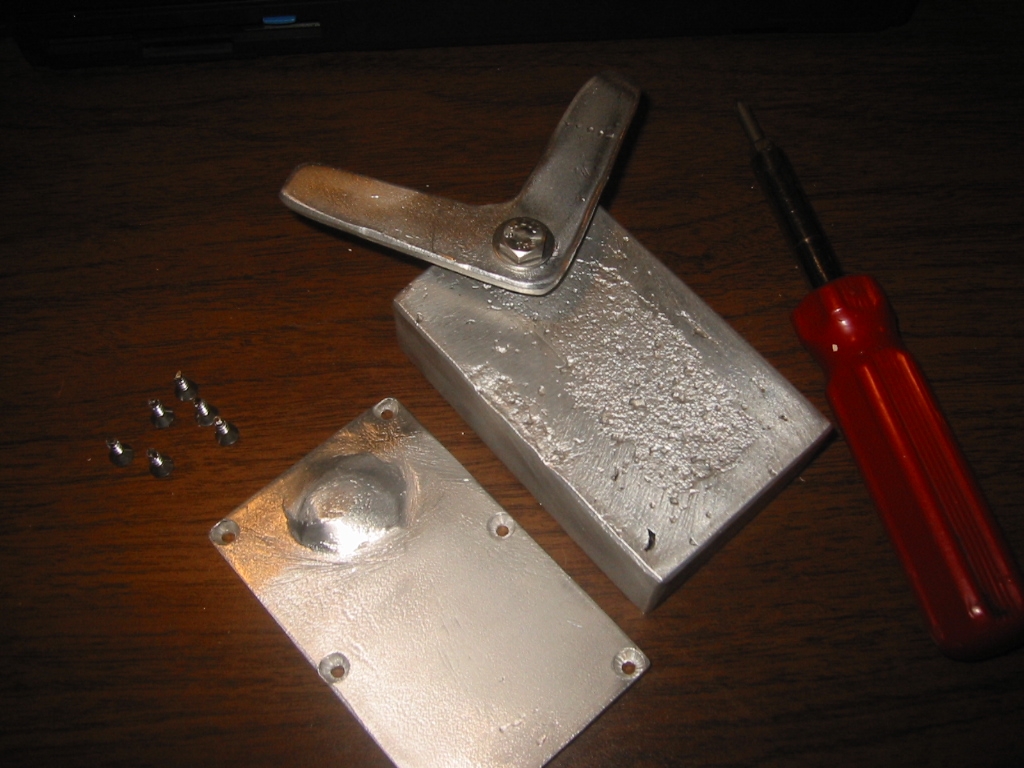
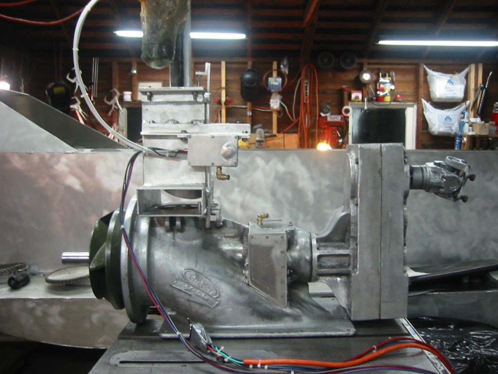
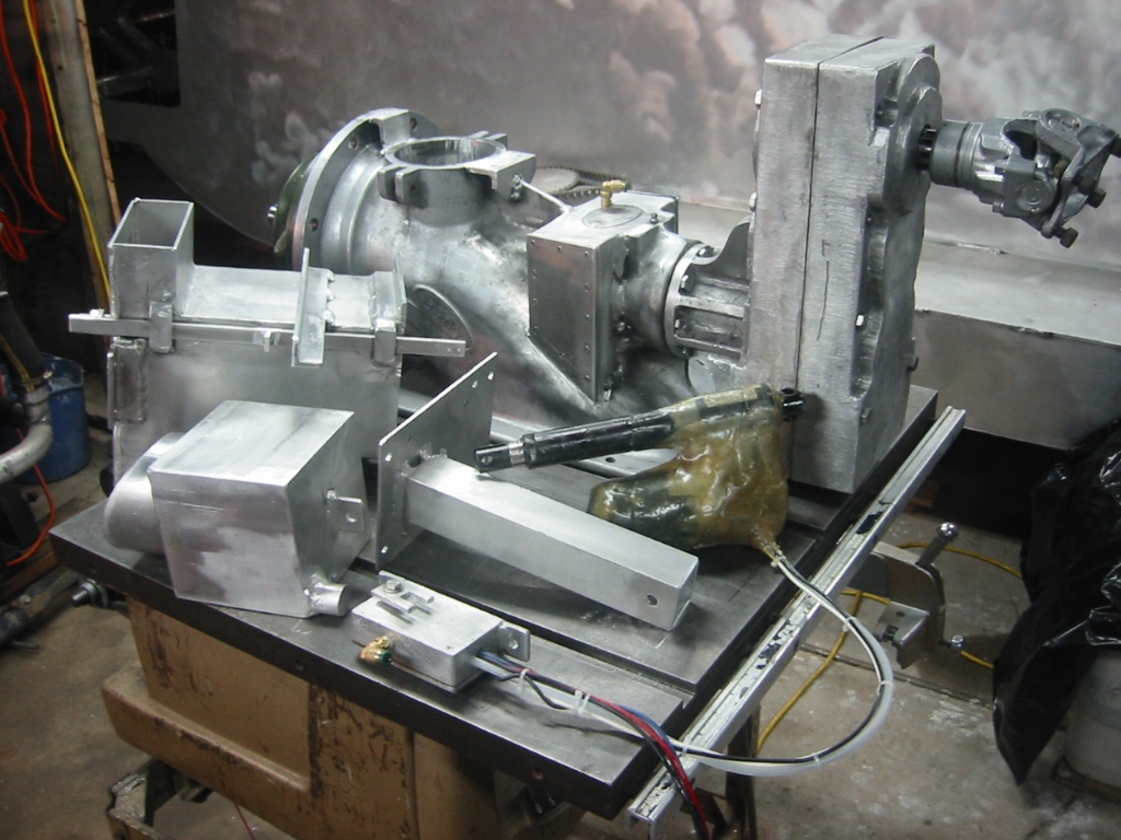
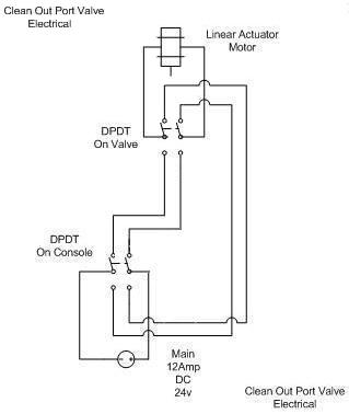
(7) I did find the perfect switch from Omron at www.omron.com and I was excited when I saw the $14 price tag, until if figured out that $14 only purchased the leaver arm, the switch was over $100. But the design of a rotating shaft that enters a sealed body is a good idea for a switch that must work underwater. I think I'll just build my own housing and let it activate a $7 toggle switch. (8) My switch box was cast from foam in about 1 hour. It's not pretty but is works. It could have been welded together too, but casting gave me the thicker sides that I needed for the screws that would hold the lid on as well as the thickness needed for a couple of o-rings that seal the rotating shaft that enters the box. The shaft for the switch first had a two pronged tab welded on. This tab will trip a simple on-on toggle switch. Then the shaft was put in the lathe where two o-ring grooves were cut as wells as a snap ring groove to keep the shaft from pulling out of the box. A 1/4 inch shoulder on the inside end will mate with a shallow hole in the lid. (9) A gentle taper on the outside end lest the two fingered leaver bind to the shaft. The shaft was drilled and threaded to take a 1/4 inch bold that holds the leaver arm securely in place. (10) The bottom of the valve will replace the current clean out port plug, but it will fit much closer than the stock clean out port plug. It is built from foam first and then cast with aluminum. (11) (12) The rest of the valve will be built from 1/8 inch aluminum sheet. It is basically a square piston with the round clean out port plug attached to the bottom. The piston moves up and down inside a box. I gave up on using a windshield wiper motor and switched to using a linier actuator. I fooled around with building my own actuator from a windshield wiper motor, aluminum pipe and all thread but gave up when I found I could but a linier actuator for $50 from eBay. The actuator was not waterproof so I wrapped it with fiberglass and added a 1/4 inch pneumatic air line that will connect backup to the ambient air supply. I also added a couple of small holes to the actuator to insure that air would reach the motor gears and piston. (11) (12) The actuator mounts on top of the valve and connects to the piston. A bar on the outside of the box will move up or down when the piston reaches either end of the box by pushing on pins that insert into the box at the corners. This bar then triggers the toggle switch. (13) The toggle switch is a Double Pole Double Through (DPDT) on-on switch and it works in conjunction with a second DPDT on-off-on toggle switch that will be mounted on the console in the cabin. When the switch on the valve is thrown it not only opens the circuit but is also reverses the polarity of the circuit so when the cabin switch is thrown again the actuator moves in the opposite direction. (14) Once mounted inside the boat I will build the channels will be extended from the valve openings to the bottom of the hull where they will be able to draw water from the lowest point. Since taking this photo I have added a neoprene gasket to the bottom of the piston so it seals tight against the bottom of the valve box when in the closed position.
|
||||||||||||||||||||||||