|
|
||||||||||||||||||||||||||||||||||||||||||||||||||||||||||||||||||||||||||||||||||||||
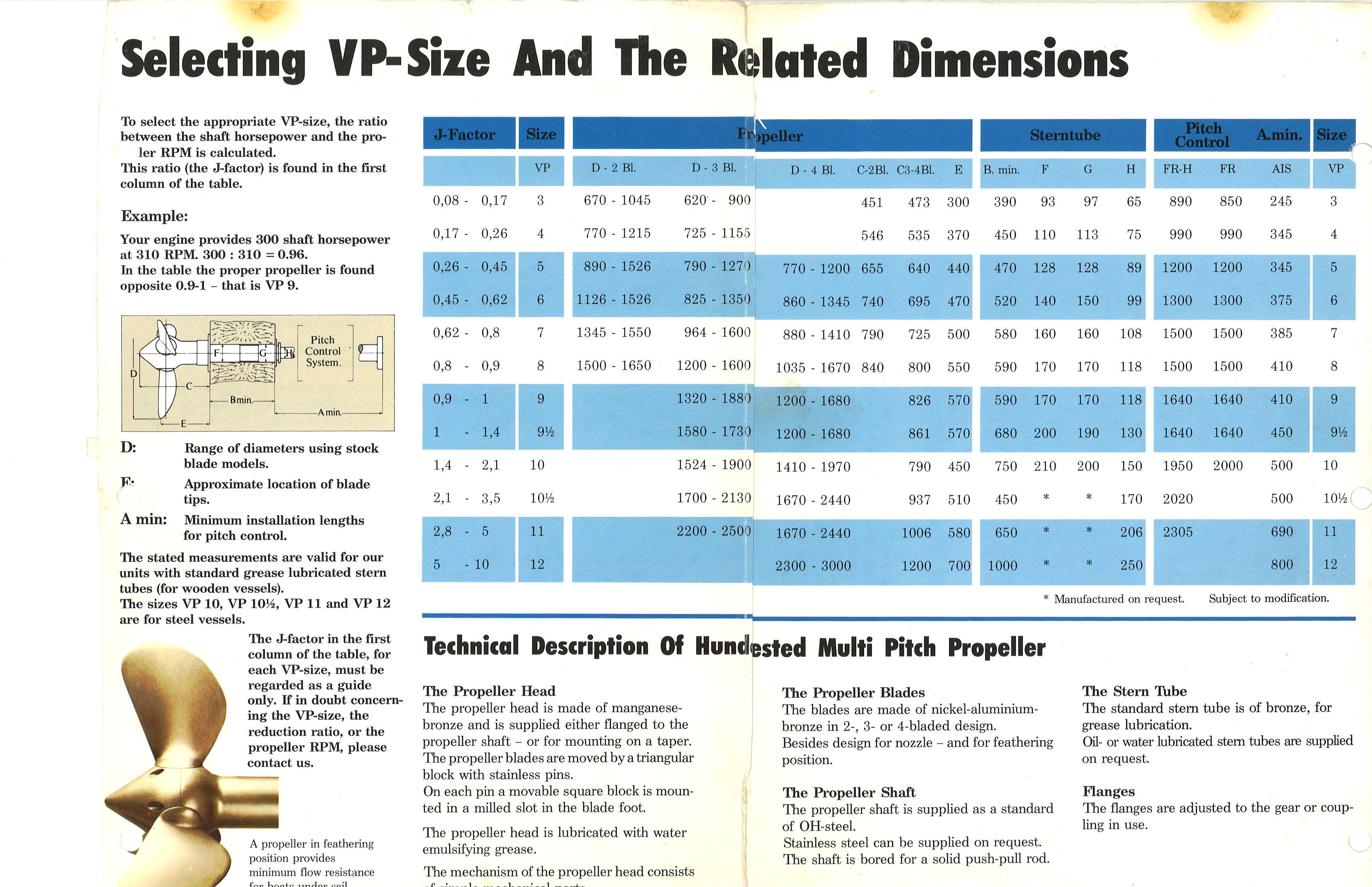
PropellerControllable Pitch Propeller (I wish)The benefits of controllable pitch propellers (CPP) specifically for a sailing/cursing/workboat. * The props speed vs. power can be adjusted according to varying
cargo loads. Typically, the drop in propeller efficiency owing to the larger boss (prop hub) size of a controllable pitch propeller is about 2 percent. However, if a controllable-pitch propeller is well designed and correctly operated, it can result in fuel savings of up to 15 percent compared with a fixed-pitch propeller operating in a nozzle. --www.fao.org The big down side to a controllable pitch prop is the cost. Hundested; www.hundestedpropeller.dk, is renown for some of the
best controllable pitch props so got a quote from McGowan Marine Inc. 1-508 990-1114
stevegow@aol.com, on a new system for a
70ft motor sailor is $66,913 plus shipping. Needless to say I am no longer looking a new Hundested drive
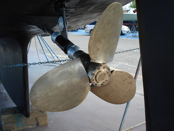
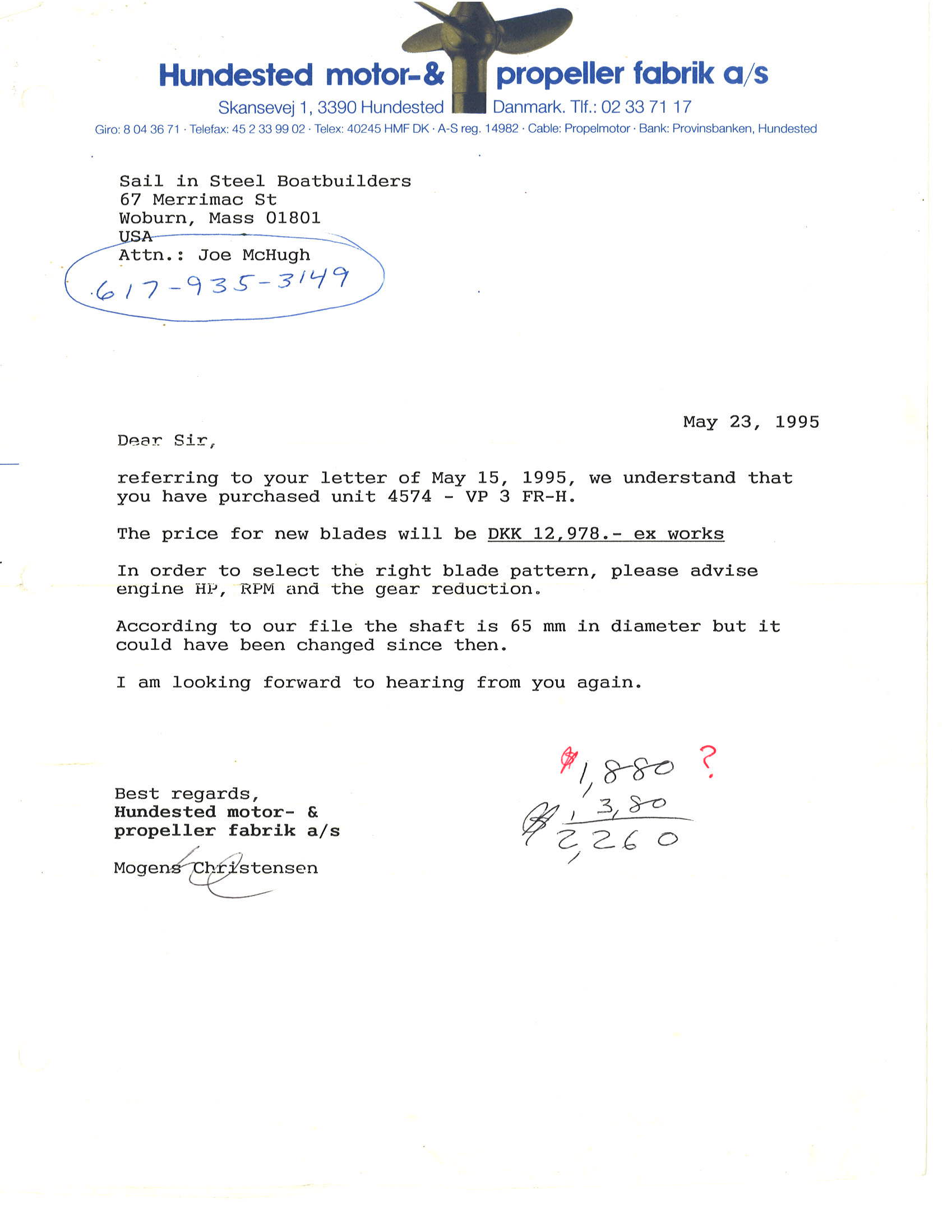
systems. Our Used Hundested CPPPaul Liebenberg sold us one of two Hundested controllable pitch propeller drives he had collected for possible use on his 65 footer. The price was great, but the problem is that we have to figure out how to make the blades that are missing. They are no longer in stock in Denmark and to have them made there will cost us close to $10,000. But the more we look at it the more it looks like casting and milling our own blades will be the thing to do. So the Hundested is getting it's own web page: Controllable Pitch
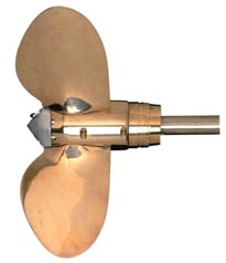
Folding or Feathering Props (Still too pricy)
If you can control the pitch at the push of a button then the next best thing for a sailboat is to fold or feather the props blades so the don't slow the boat down when it's under sail power. Max-Prop; www.max-prop.com manufactures and sells a self feathering props in a range of blade configurations. I'd love to have one, but our boat would require a 35", 3 blade propeller and the cost is $15,500. And being a workboat I doubt it would be very long before I was needing to replace a blade or two due to damage caused by operator error.
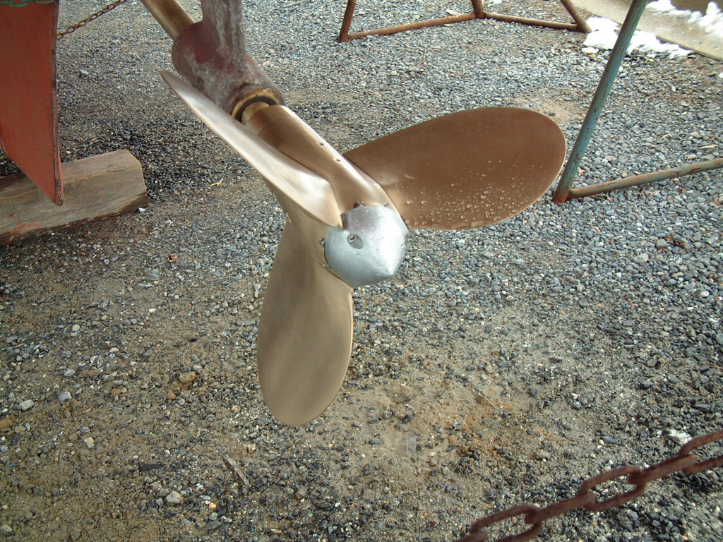
Affordable Fixed Pitch Props (Better)Buying a Prop
If you live on the coast this will be a piece of cake, but if you live in Tulsa, Oklahoma you will likely have to shop by email. Brent Swain's advise "Get a prop within 4 inches of the pitch you want, preferably closer. Any more and if you try to re-pitch a prop more than 4 inches the blade breaks off." To test a used prop is to rest it on the hub and then tap the end of each blade. It should produce a clear ringing. If it is dull and short lived then pass it up. CraigsList turned up more than a few props down toward New Orleans, so they are out there. Check: www.propellerplace.com A new 36" bronze prop from deepblueyachtsupply.com is $3,610. Another option is a new stainless steel prop from Kahlenberg
propeller that is intended for use on work boats. We plan to
frequently work in shallow waters and close to obstacles so a
stronger prop might be worth the extra money. The price for Kevin Morin builds boats up in Alaska and he highly recommended stainless steel wheels; "My examples were fishing commercially, justification for these wheels was their ability to run in gravel bars of Bristol Bay and keep running without damage." RotationMost engines are left hand rotation. Meaning that if you look at the engine's fly wheel from the back it will rotate counter clockwise, or the top of the flywheel will be moving toward the left. Also most inboard props are left hand meaning they push the boat forward when they spin counter clockwise as seen from the back end. Prop SizingA good place to start is with some of the manufacturers sites like Michigan Wheel: www.miwheel.com/propellers/prop-it-right/ Max allowable propeller diameter 34" - 36" Need 10%
clearance between the blade tip and bottom to reduce noise. Using a Cummins C8.3 210 hp, 2400 max rpm, 446 lbft @ 1300
rpm From Dave Gerr's book "Boat Mechanical Systems Handbook" Minimum Blade Area & Diameter for Displacement Hulls Prop Tip to Bottom of Hull = .2 * prop diameter 37.0 =
7.5 inches Rough Shaft Diameter = 1/15 * prop diameter 37.0 = 2.5 inches Shaft Dia = cubrt( (321,000 * 200 hp * .96 [shaft hp] * 4 Safety
Factor) / ( 20,000 psi yield strength 304 stainless * 725 rpm)) Shaft Bearing Spacing if feet = 4.6 * sqrt( Shaft Dia ) Thrust Pounds = ( 326 * shaft hp [200 * .96] * displacement hull
propeller efficiency .55 ) / ( .9 * knots 10 ) From Dave Gerr's "Propeller Handbook" Torque = (5,252 * hp) / rpm Hull Speed = 1.34 * sqrt ( water line
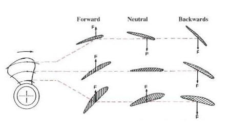
length ) SL Ratio - Speed / Length or theoretical hull speed when the wave length is equal to the waterline length. Kts =11 Desired Speed in knots Pitch and angle of the blade are not the same. Consider that the root of the blade closest to the boss cuts through much less water in one revolution than does the tip of the blade. So the tip of the blade has a much smaller angle to the shaft that the root. If both the tip and the root are pitched the same then both would travel the same distance through the water when given one rotation. Building a Steel Propeller from Scratch ( Yeah Baby - Field Repairable )I came across a bit below in the Wylo-II group from Lex
Hodgkinson. Lex is using a 1.8 to 1 Hurth gearbox, so the 3000 engine RPM is 1666 at the prop. "The prop was built using a simple steel jig to compare the blade shapes to ensure they were the same and at right angles to each other, pitch was checked at two or three locations with more attention paid to the outer 1/4 and the tips. Balance was checked simply by mounting on centers and grinding to achieve no bias. The blades with some reinforcement at the roots were mounted into slots cut into a 2"dia hub which was drilled to 1 1/4" to accept the shaft. The hub is welded to the shaft only at the aft end." --Lex. Our prop is 36", not 17" so we got a bit more force involved in order to pitch the blades. They make special anvil called a "pitch block" for hammering a prop into shape, but that's for smaller speed boat props. However a pattern would be really helpful when bending the blades. VibratorsThe frequency in Hz transmitted by the propeller to the hull is
given by So our 3 blade prop turning at 500 cruising to 719 RPM running at
wide open throttle gives us an frequency from 25 to 36Hz. If we
dropped to 2 blades, that would be 17 to 24Hz. Stuffing Box / Shaft Seal
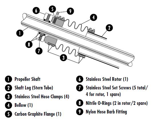
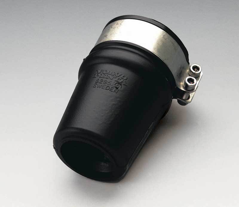
PSS Dripless Shaft Seals are a popular choice but they do leak when shifting directions if the shaft has any slip in a thrust bearing, and they are also $440 for a 2" shaft. For me the down side is that the PSS is not designed for contact with oil or grease and I may want to use a mild steel driveshaft and protect it by sealing the outboard end of the shaft log and flooding the log with oil. Volvo Penta makes a Rubber Stuffing Box for 2" shafts with 2 3/4” sleeves which sell for $165 (2010). They say to grease it every 200 hours so it should be fine to flood the shaft log with oil. The requirement for a 2 3/4" sleeve is a bit of a problem too as a 2 1/2" pipe has an OD of 2.88". Water resistant grease is applied to the inside of the seal by squeezing the sleeve to vent it and then applying the grease to the inside. A Traditional Stuffing Box, drips, and we don't want the drip, especially if we flood the shaft log with oil to protect the log and steel shaft. Seeker's Prop & Drive Under ConsiderationShaft 2" Mild Steel with 1:10 Taper Prop Resources
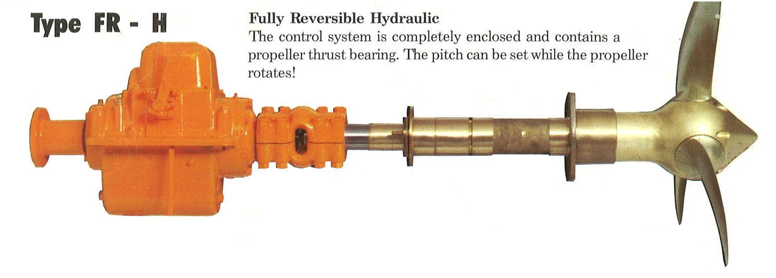
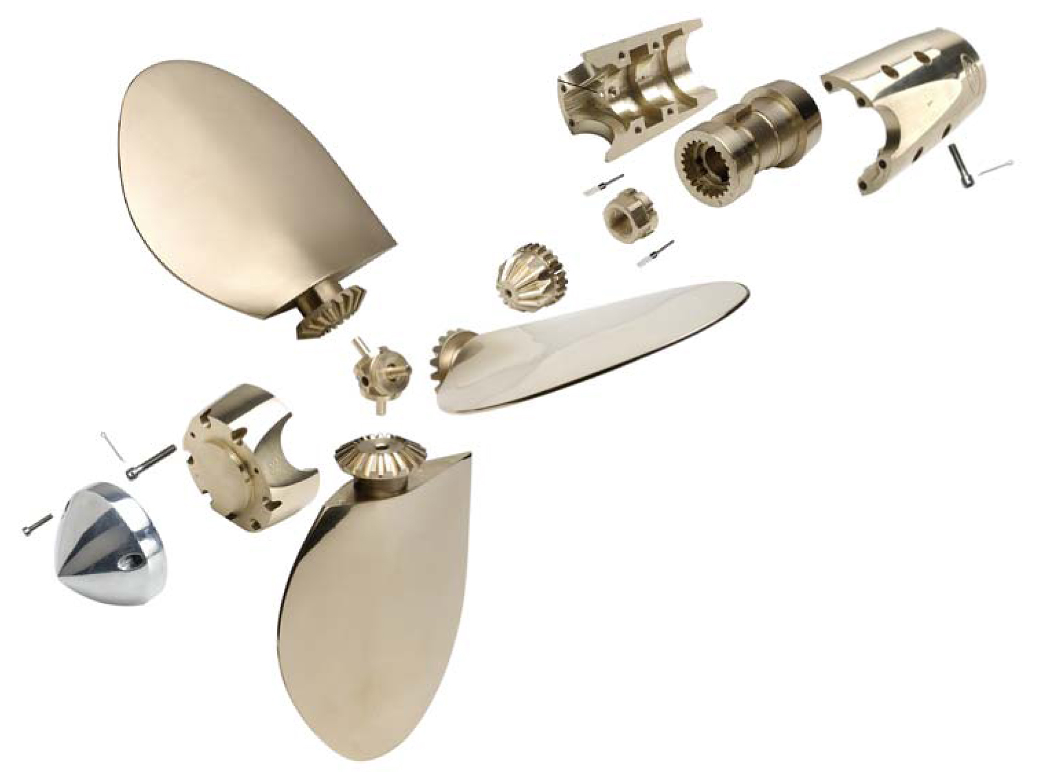
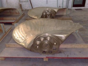
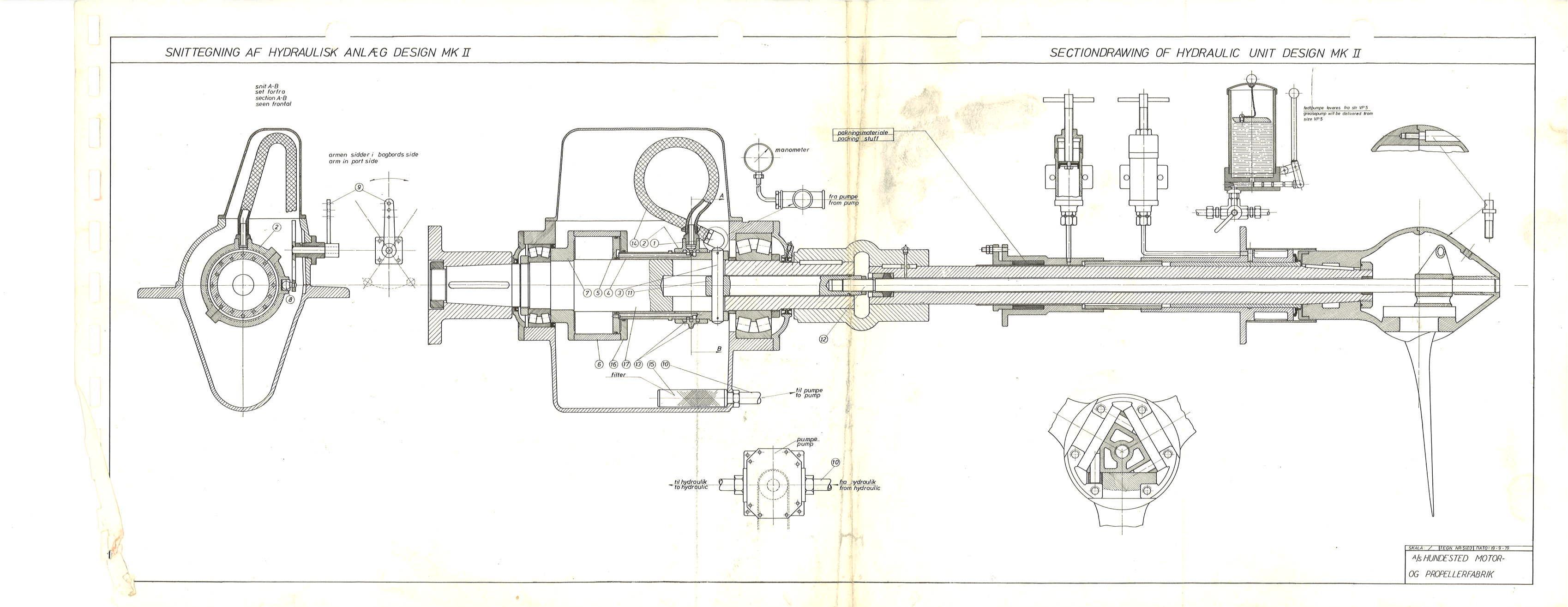
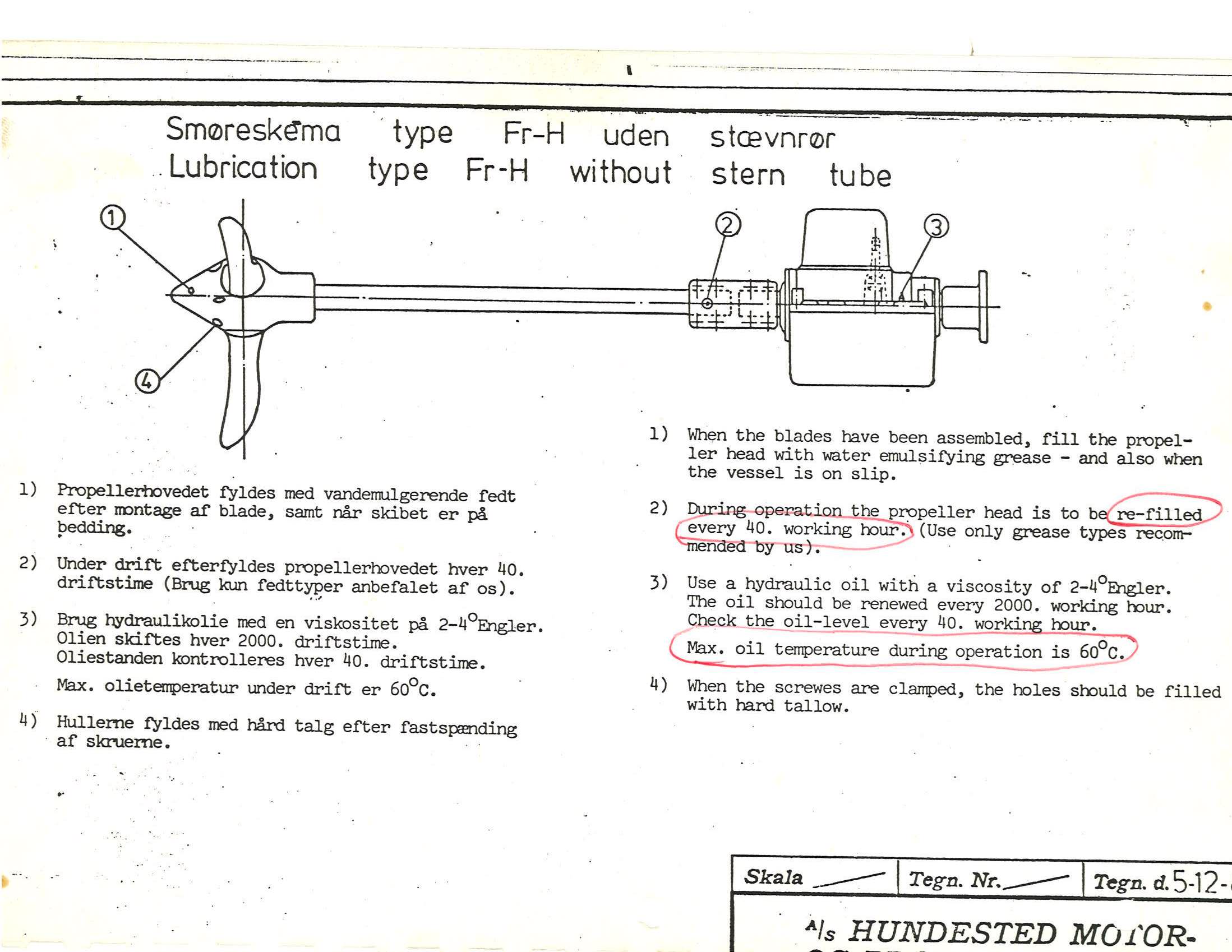
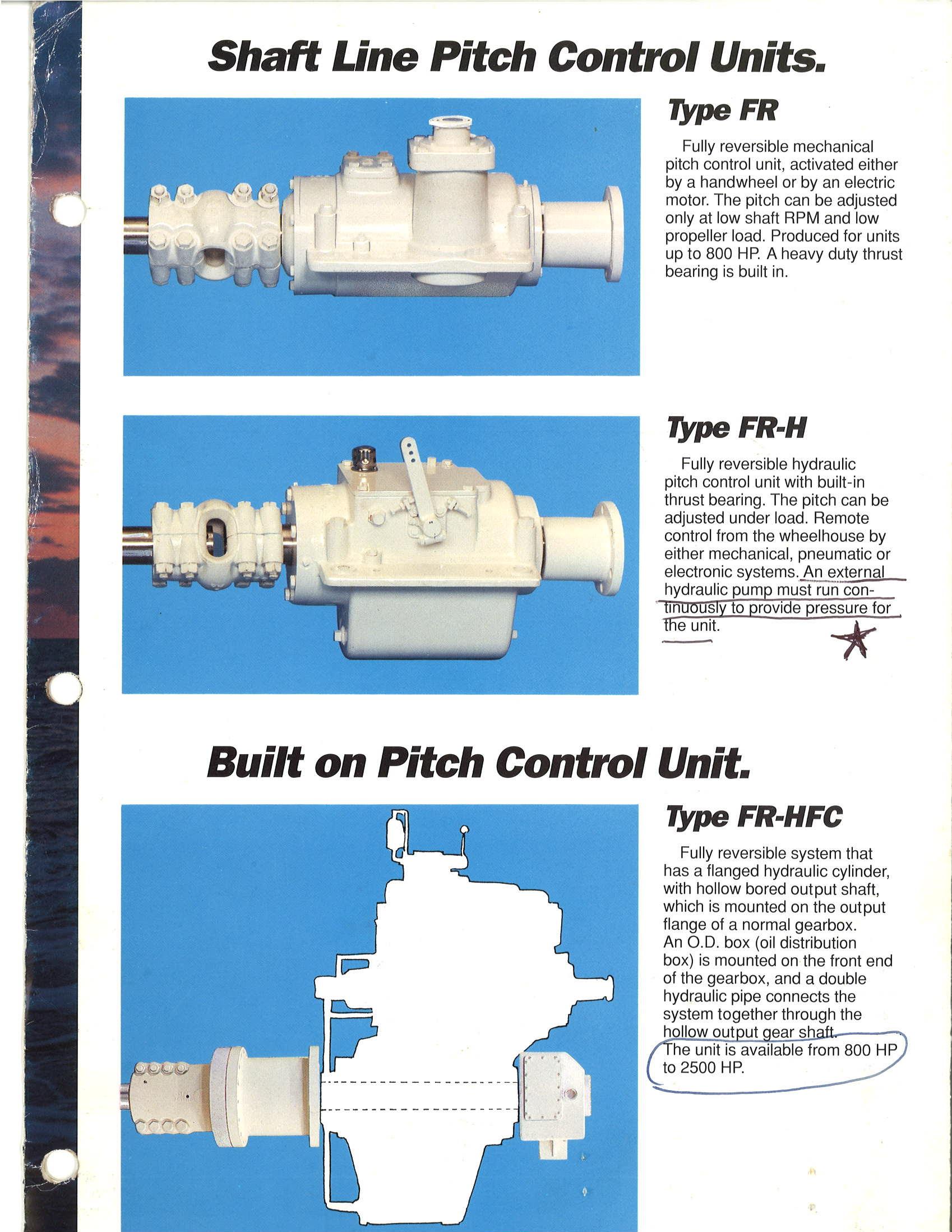
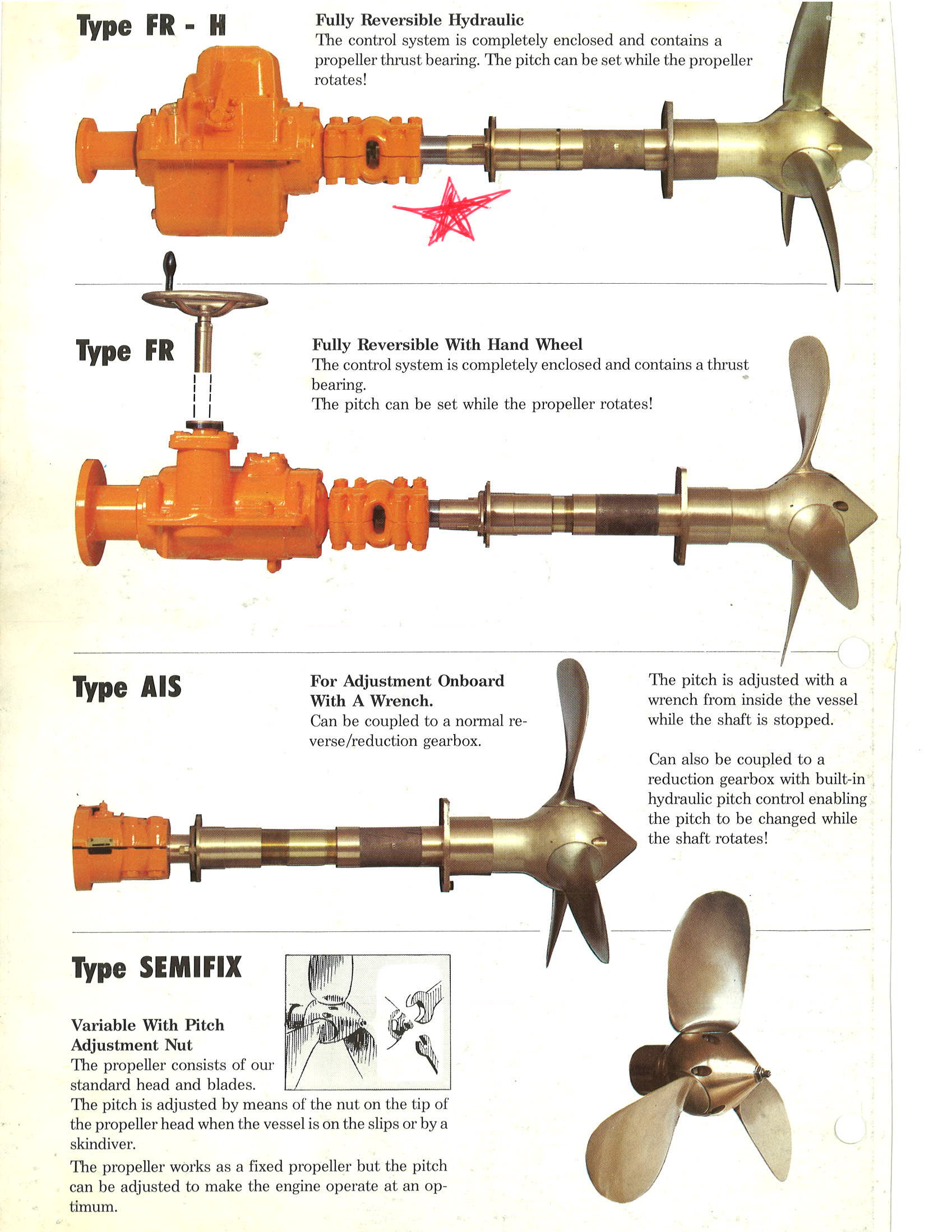
www.boatdiesel.com Hundested Controllable Pitch PropSo we have all of the working bits except for the blades. We could go with stainless steel plate bent to shape and welded onto lathed stainless bar. Or we can go for a closer proximity to the original and cast our own from scrap props. Why Controllable Pitch?Used Hundested VP-3 FR-H Teardown
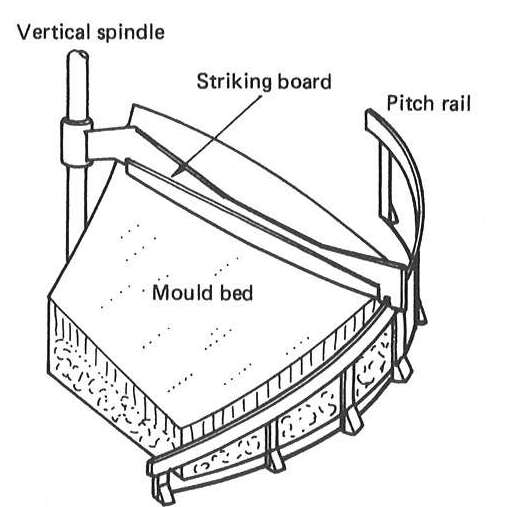
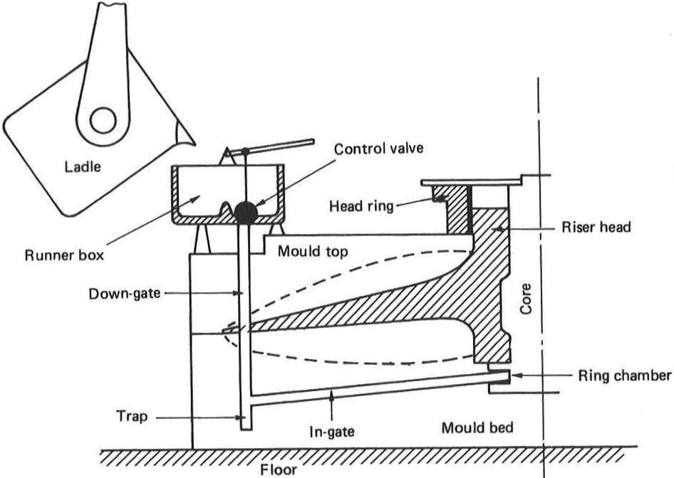
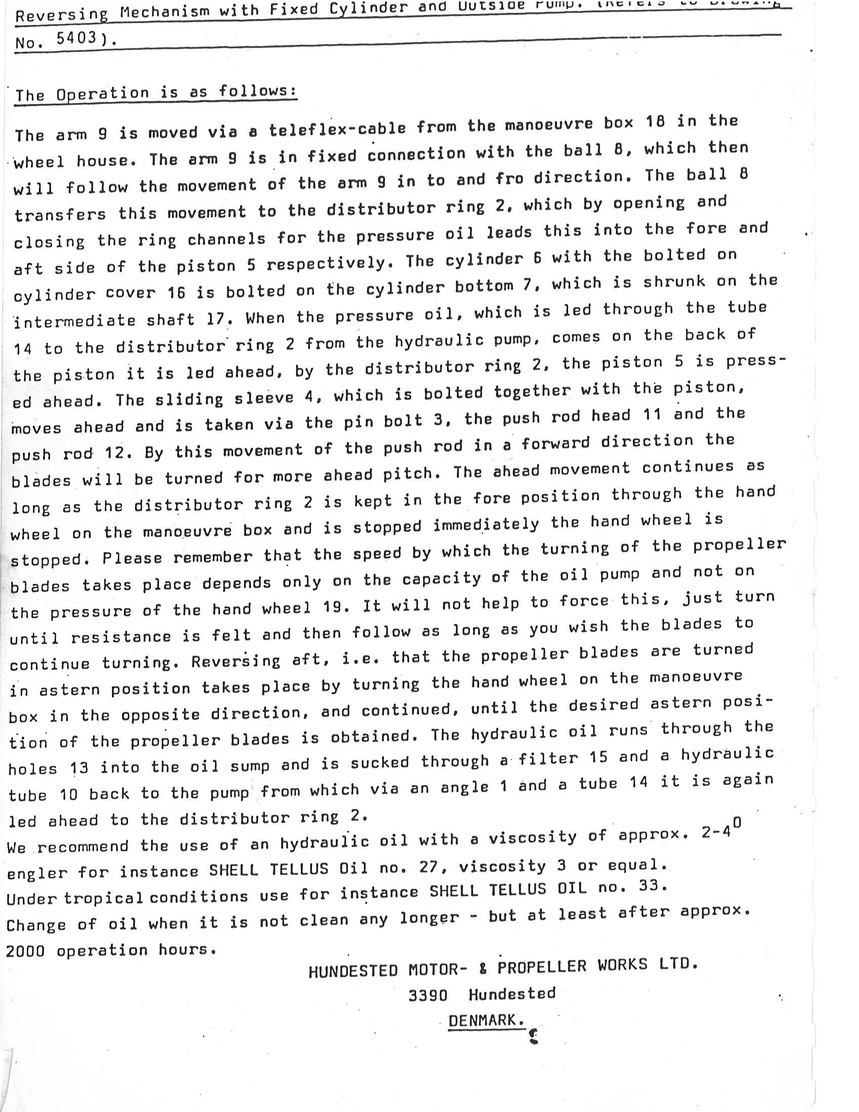
The weather is getting colder so we moved the Hundested inside and starting taking it apart and cleaning it up. Unfortunately we discovered that their is a collar for the hydraulic system missing from the controller. The real name from this is the distributor ring. For support for Hundested you can actually call Mogens Christensen in Denmark who now owns the Hundested company. Or you can call Joel with Pacific Marine Equipment Sales in Seattle at 1-206 281 9841 . I've spoken to both, and both are very helpful, but Joel understands my Oki accent better. :) How Ship Propeller Blades are Cast
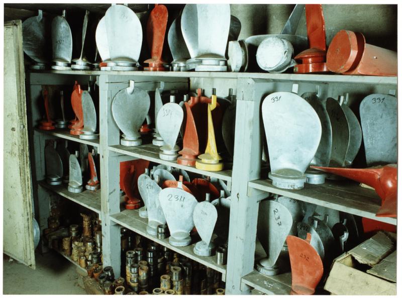
These illustrations from Marine Propellers and Propulsion show how propellers were traditionally molded and cast.
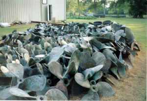
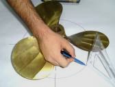
I contacted Brain at Boat City Prop Shop in Oklahoma City. And he'll sell us the Nibral out of his pile of scrap props for scrap metal prices. So the next step is to start on a CAD design that approximates the original blades, but with the diameter and surface area appropriate for our boat. Propeller Blade DesignBackground
Examples for Variable Pitch Props
Resources:
http://charlesroring.blogspot.com/2010_02_01_archive.html
http://www.propellerpages.com/?c=articles&f=2006-03-27_manual_pitch_measurement
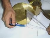
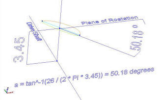
Formula Pitch Angle for a Desired PitchIn order to design a prop of Seeker in CAD we need to find the pitch angle that will create a desired pitch. Pitch Angle is the angle of the pressure face along the line from the leading edge to the trailing edge at a given radius with respect to the plane of rotation measured in degrees. Pitch angle decreases from the blade root to the tip in order to maintain constant pitch. Finding Pitch Angle:
http://www.halepropeller.com/PropellerTerminology.html Need a great calculator? Use: http://www.wolframalpha.com
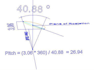
The formula for the pitch angle at a specific radius for a desired pitch. Pitch angle = tan^-1( Pitch / (2Pi r) ) where: r = radius So the root of our blade is 3.45" from the center of the hub or r = 3.45, and desired pitch is 26, so: a = tan^-1(26 / (2 * Pi * 3.45)) = 50.18 We can then check it using the Manually Measuring Prop Pitch formula above: Pitch = (Difference between the leading and trailing edges of the blade * 360 degrees) / angle formed between the center of the hub and each of the two measured points. Pitch = (3.06 * 360) / 40.88 = 26.94 ( close enough for me)
Next the skin is applied. The nipple on the top was added to remove distortion in the skin due to the quick change in shape. It will be cut away later. The normal load on each blade is just under 1,300 pounds and the cross section of the root without any fillet is 3.74 sq in.
|


|
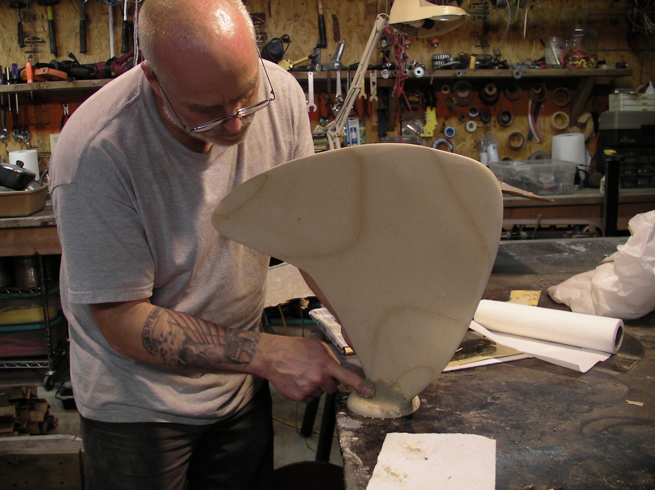
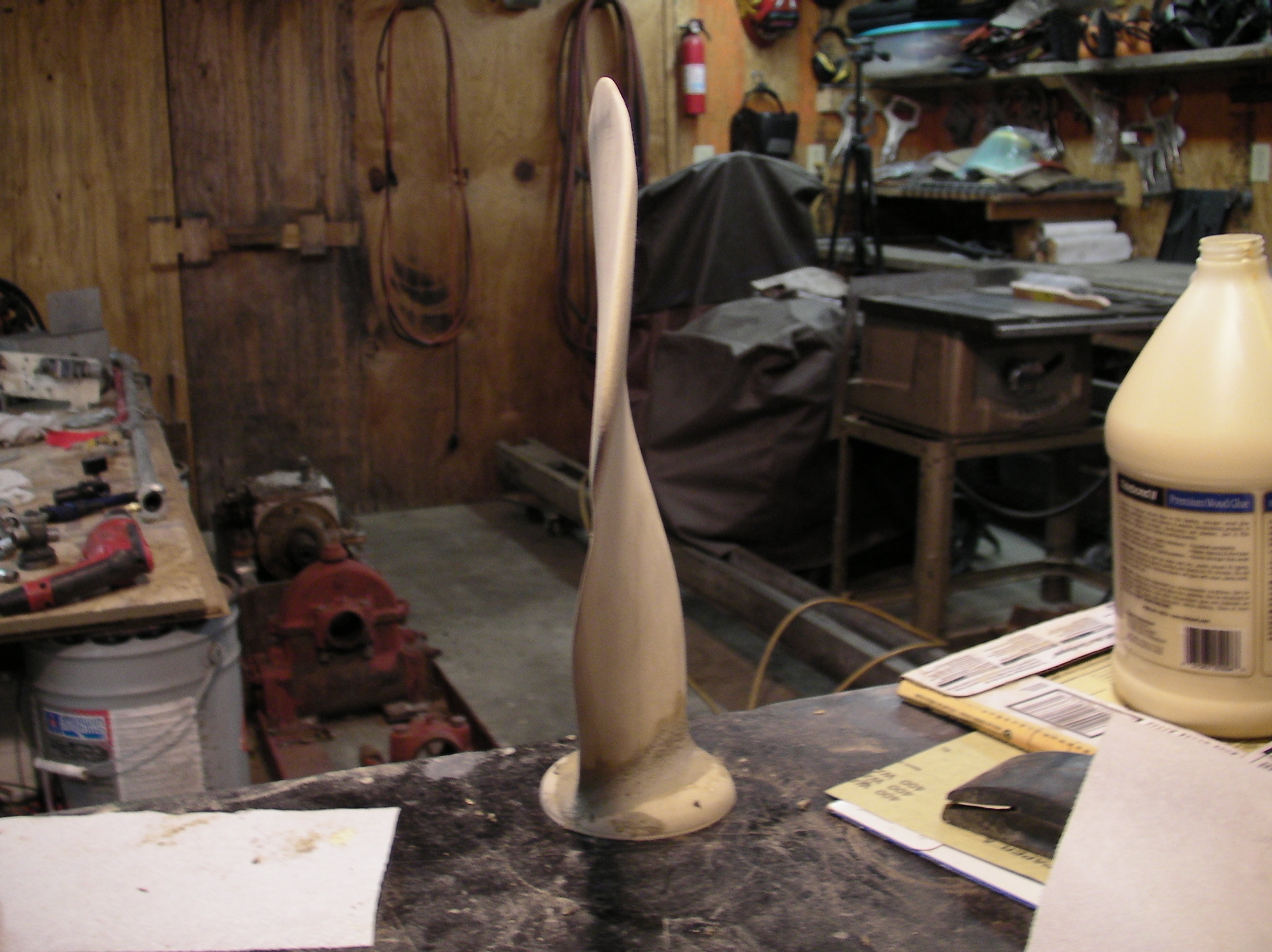
After four test or or failed attempts we got a pattern cut from MDF, or fiberboard.
There is some unwanted high spots on the blade due to the BobCAD software. It did fine where the changes are gradual but it make the tip thinker than planned. However the MDF sands down easily and a slightly thinker tip may be a good improvement when doing battle with sand and gravel.
Propeller Materials
NiBrAl Cast Material = 0.2745674 lbs/cu inch * 193 cu inches * .5 in avg blade thickness = approximately 27 pounds in the blade + 8 pounds for the gating system or about 35 pounds.
Stainless Steel Bolts: Mertensitic, Hardened and Tempered (HT),
410 or 416 HT. These aren't as corrosion resistant.
http://www.americanboltcorp.com/astm/grade_markings.htm
Read more: Stainless Steel Bolt Loads & Strengths | eHow.co.uk
http://www.ehow.co.uk/list_6547611_stainless-steel-bolt-loads-strengths.html#ixzz1a9k4plhF
Needed:
Pyro Meter
http://www.budgetcastingsupply.com/Pyrometer.php BCS #7410
Digital Meter, $49
or use a Volt Meter and the
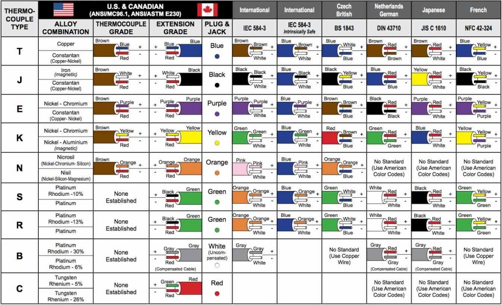
Type K Probe Millivolt to Fahrenheit chart.
Tool & Probe release agent,
http://www.budgetcastingsupply.com/Marcote-7.php #1050 Marcote 7
Refractory Coating, $22.50
Probe: McMaster-Carr
http://www.mcmaster.com Extended-Life Thermocouple Probes, 24",
Number: 3859K46 $10.87 each
or:
http://mifco.com/MS/catalog.php?op=detailed&id=175
or:
http://www.omega.ca/shop/pptsc.asp?ref=TJ36-XCiB_chb&flag=1
|
leave the dross on the melt, when you pout have then push it back
Borax for flux or Boric Acid with Sodium Carbonate 50 50 mix
flux tool to push the flux under the surface
clay-graphite crucible, Or coat a steel crucible with Marcote-7 or
ITC-100
skimmer gate
ceramic filter
www.ransom-randolph.com
www.tower-packing.com
Randupson Portland Cement -- Portland Cement can be and is used as a
bonding agent. Known as the Randupson process, it concerns the use
of 15 and 20 mesh, washed silica sand mixed with 10% cement and
approximately 5% water. Moulds should be air dried for twenty-four
hours and may then be dried out more rapidly. Dry mix for 5
minutes then add the water. The mould is formed around the
pattern and allowed to air dry for 24 hours. Once the pattern
is removed the mould can be dried with hot air. The blade is cast
flat with the boss end making the spure and a vent at the tip. Prior
to pouring the mould is preheated the exhaust from the vent
temperature is 245 degrees F. The gate is located at the
bottom of the boss so as to allow the molten metal to rise gently
into the mould which reduces turbulence and so minimizes oxide
formation.
Casting temperature for NiBrAl is 2048F (1120C) to 2300F
(1260C). Rapid cooling of the casting will improved tensile
properties. Contraction will be 2% in the heavy boss section and
less than 1/5% in the blade tip.
Volume 0.2745674 lbs/cu inch
Nickel Aluminum Bronze; Ni-Al Bz, also called "Nibral" and frequently miss spelled as "Nibrill", has a melting point of 1913 to 1940F. AA Num: 95800
|

Resources
http://www.copperinfo.co.uk/alloys/bronze/downloads/pub-81-designing-aluminium-bronze-castings.pdf
R & D Pattern & Foundry Co
711 South Wheeling Avenue, Tulsa, OK 74104-3215
(918) 587-2095
Ni Al Bz Ingot Suppliers
Atlas Bronze, Trenton, NJ
www.atlasbronze.com
800-478-0887
Federal Metal, Bedford, Ohio
www.federalmetal.com
800.736.6636
|
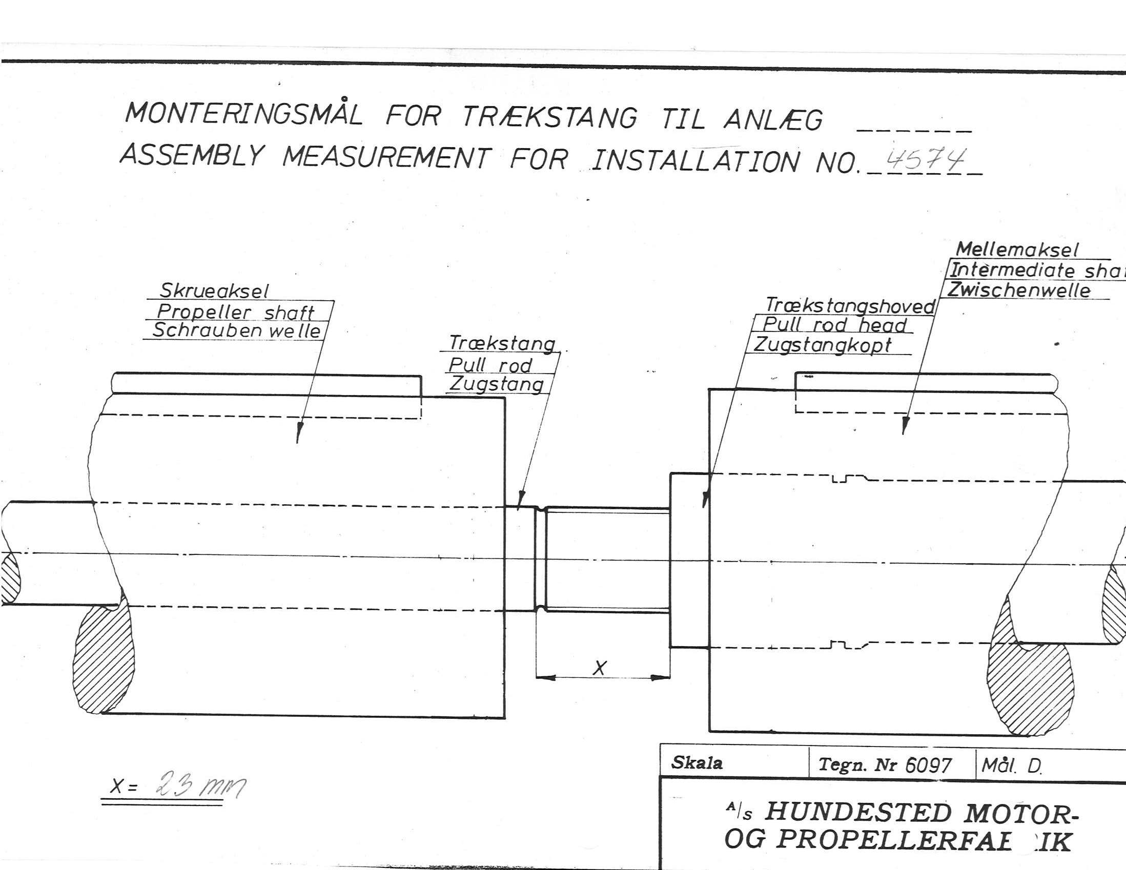
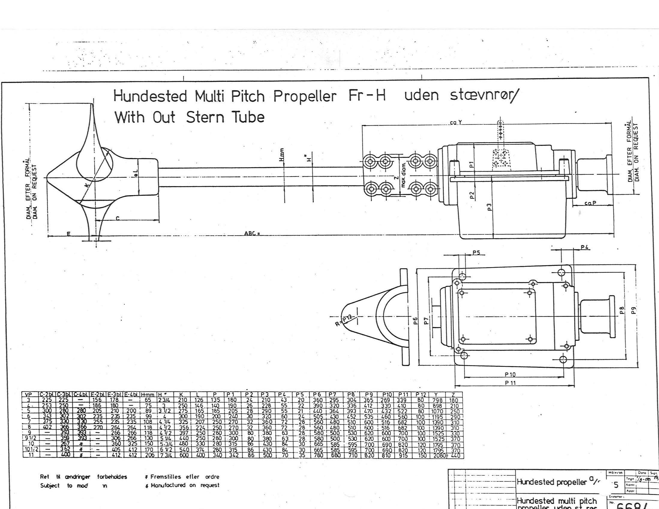
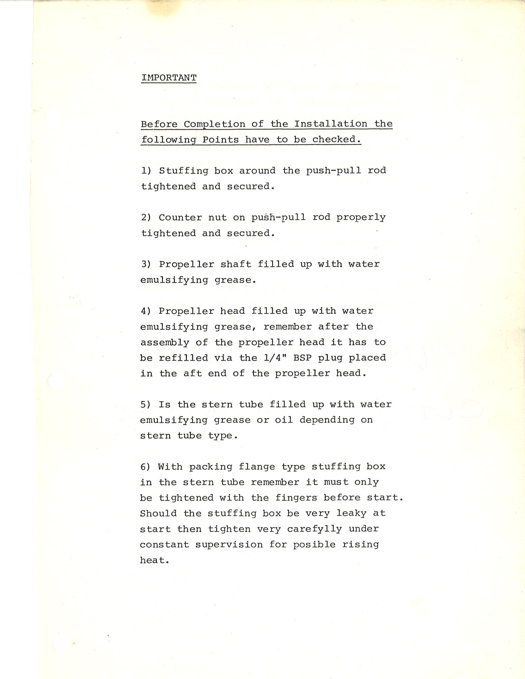
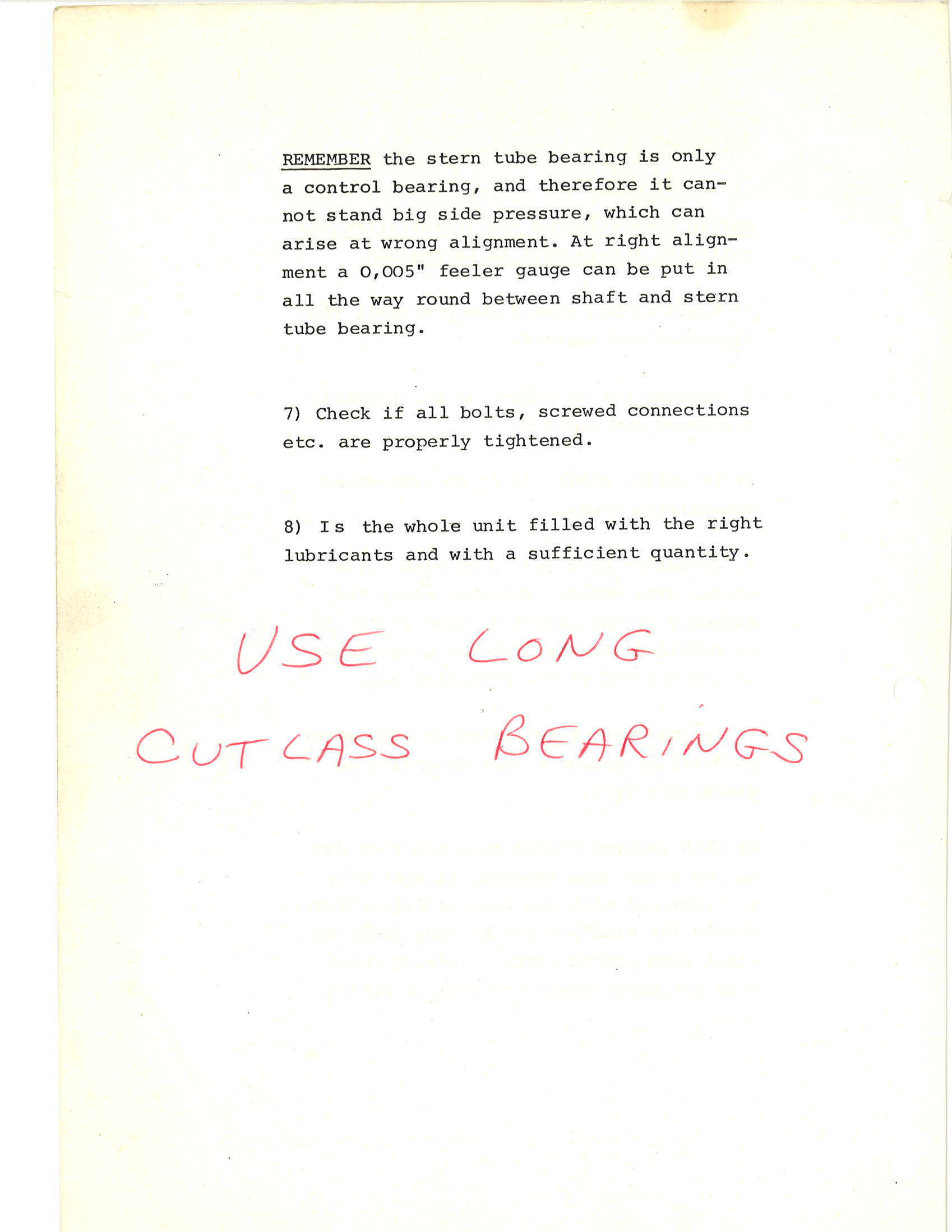
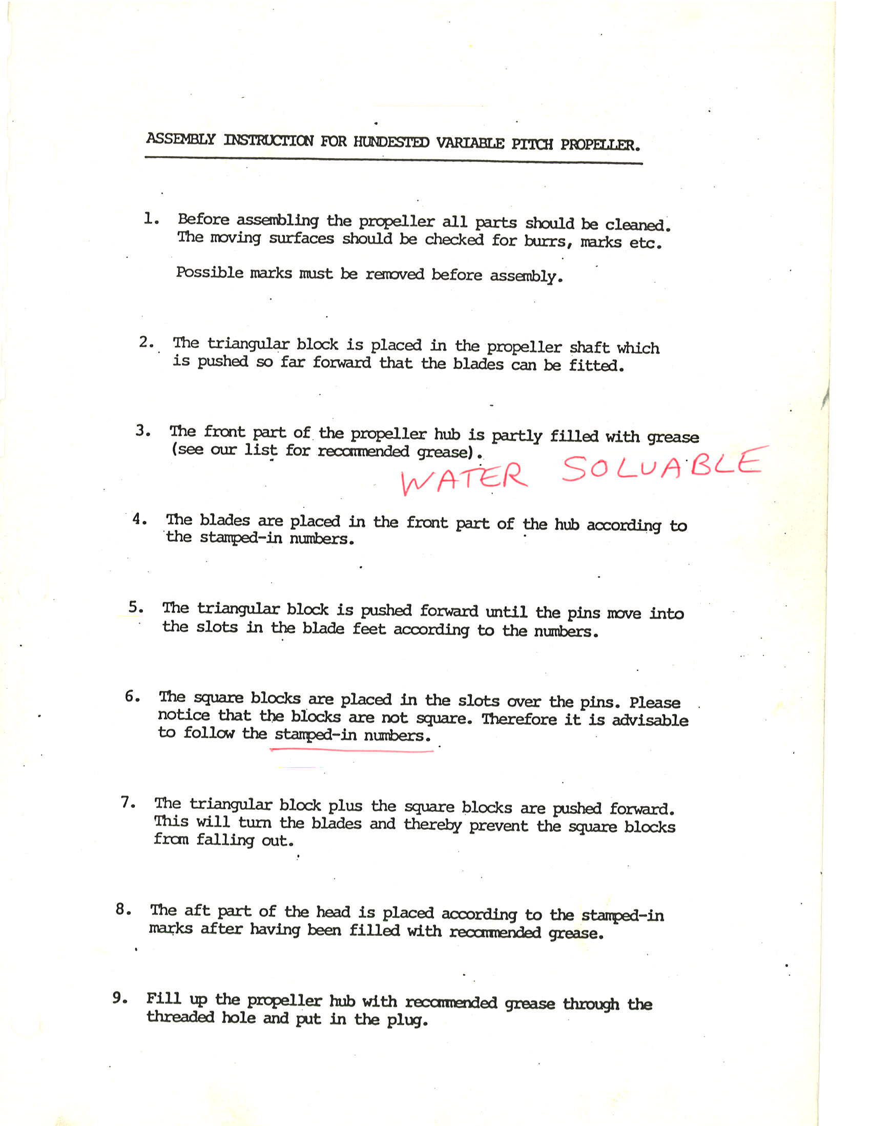
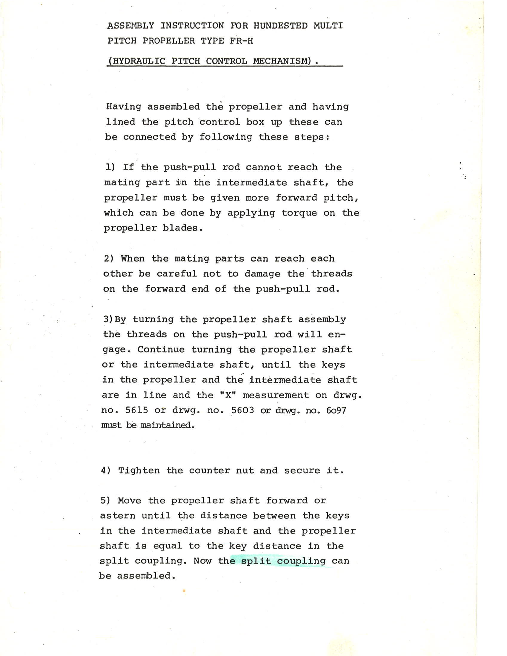
Hundested V-3 FR-H Documentation
Manufacture Number: 4574
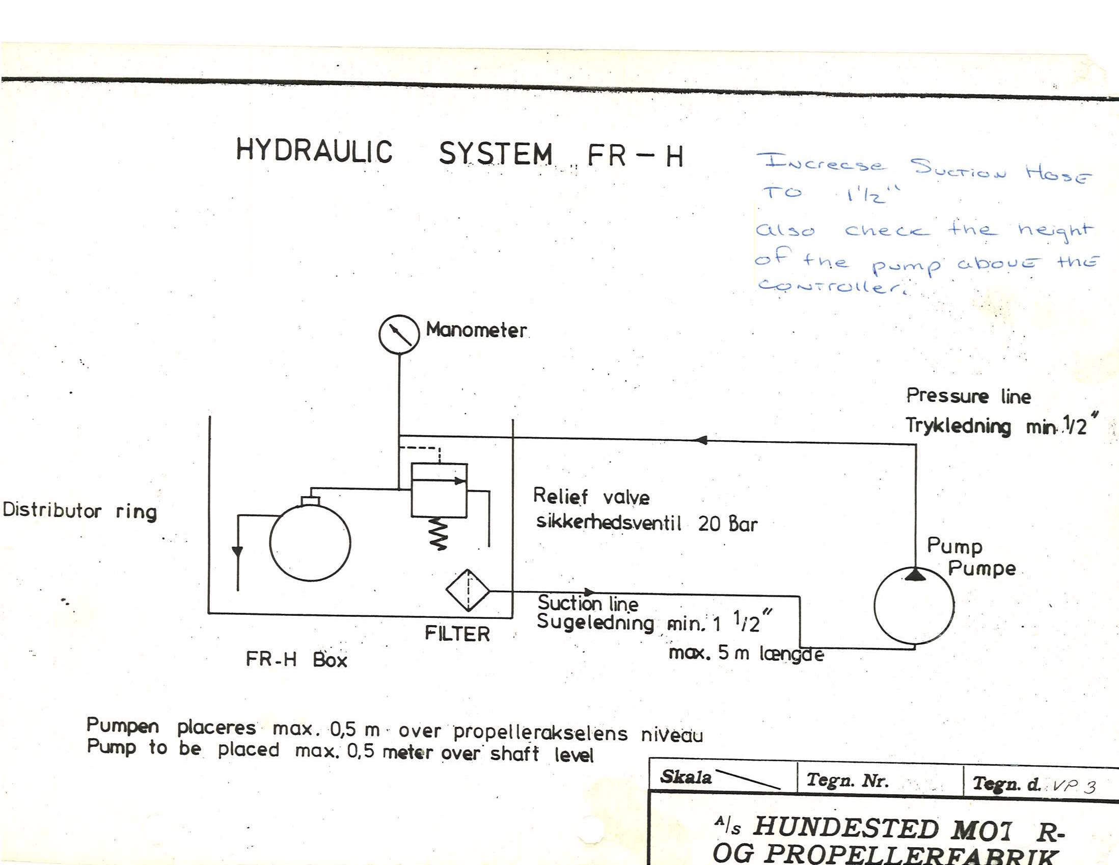
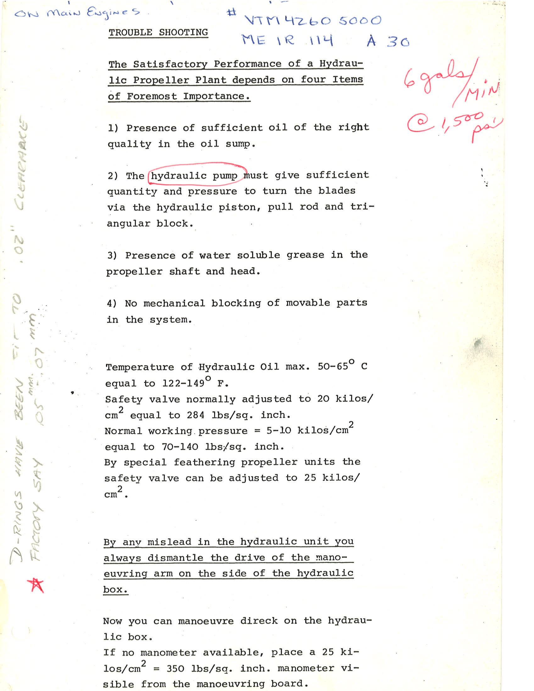
Hydraulic pump maximum 19 inches above shaft.
Return line: 1.5" Pressure Line: .5"
Flow rate: 4 to 6.5 gallons / minute
Normal pressure: 70 to 140 psi
Relief pressure: 20 bar, 290 psi
Use 350 psi hydraulic pressure gauge on console.
Maximum hydraulic oil temperature 122 to 149 F.
Replace after 2000 hours or 2 years.
Hub material is magnesium bronze.
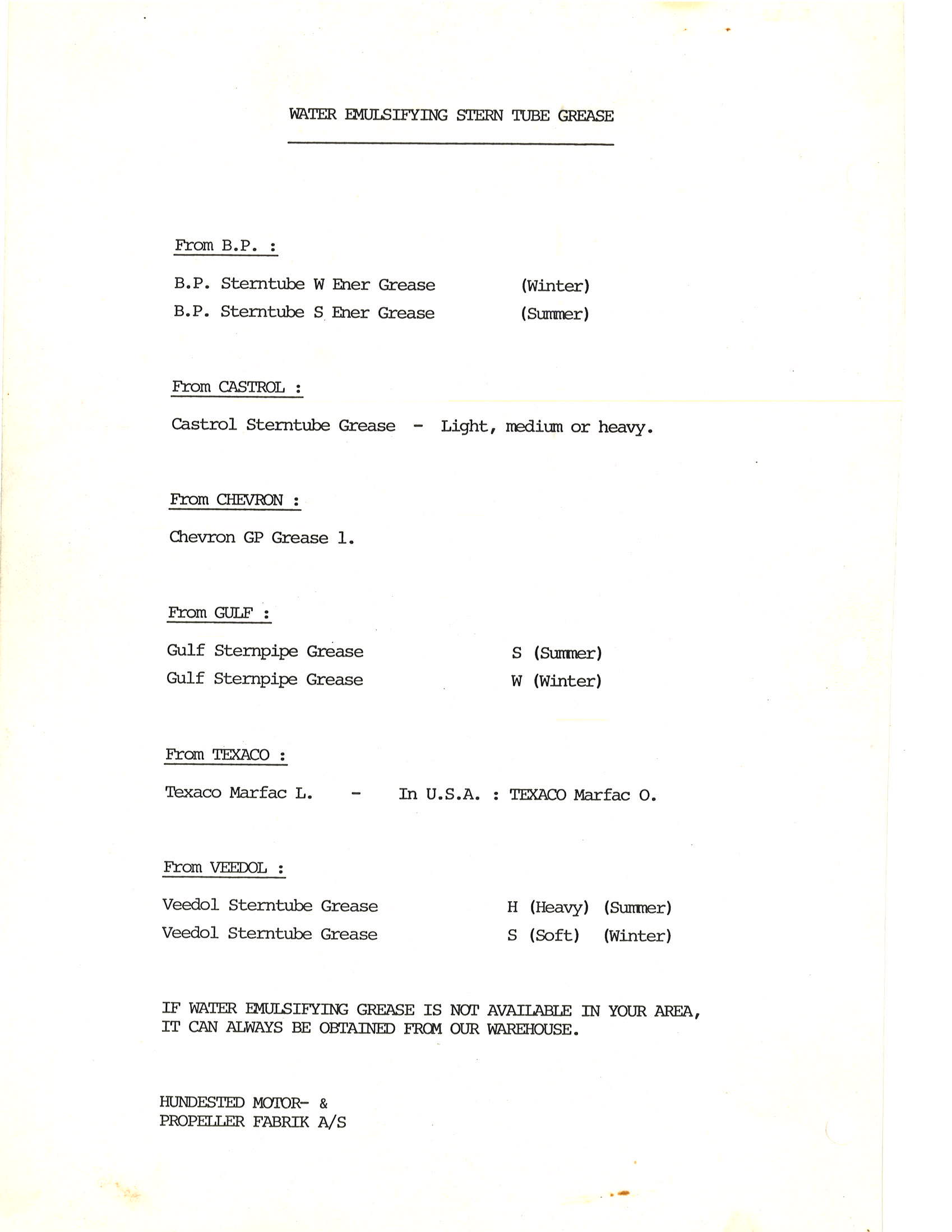
Hub and internal shaft uses water soluble.
Fill bolt holes with hard tallow, or machinable wax.
Use long cutlass bearing.
Shaft diameter: 65 mm
Propeller shaft to controller shaft alignment: .03 to .05 over 9.75"
Hydraulic oil degrees englar (E): 2 - 4
Mobil DTE light or DTE 24
Shell Turbo T32 or Tellus Plus 32
Texaco Regal R&O 32 or Rando HD 32
Conoco Hydroclear R&O 32 or Hydroclear AW 32
Hydraulic Supply
Cummins Power Steering Pump: Zahnradfabrik Friedrichshafen Type
76749?4150
Parker Cartridge Valves and Bodies from Aberdine Dynamics, Tulsa
OK. 918 437 8000
Parker Cartridge
Specifications
Parker: Pilot Operated Pressure Reducing Valve
Primary Bypass - Adjust to open at 290 psi and supply other
equipment or dump back to Hundersted controller.
This simulates an autotive steering system that dumps excess when
the wheels are not being turned.
PRH082S10 $52.00 Pilot Operated Pressure Reducing Valve: 100 - 1000 psi, 8 gpm, 80 psi drop. Max 200F, Cartridge 3-port B08-3-A6T $27.50
3 port aluminum body for cartridge B08-3-A6T 3/8"
Parker: Pilot Operated Relief Valve
Regulates pressure suppled to controller to 290 psi, when the
controller is not using the supply the primary bypass will open
dump the excess pressure and flow.
RAH081S20 $48.50 Pilot Operated Relief Valve, 100 - 2000 psi
B08-2-A6T $19 Body 2-ports, 3/8" O-ring Port
Parts
Aft thrust bearing: Koyo 6413
Forward thrust bearing: Koyo 6315
|
![]()