|
|
|||||||||||||||||||||||||||||||||||||||||||||||||||||||||||||||||||||||||||||||||||||||||||||||||||||||||||||||||||||||||||||||||||||||||||||||||||||||||||||||||||||||||||||||||||||||||||||||||||||||||||||||||||||||||||||||||||||||||||||||||||||||||||||||||||||||||||||||||||||||||||||||||||||||||||||||||||||||||||||||||||||||||||||||||||||||||||||||||||||||||||||||||||||||||||||
Wiring Harness
Unplugged
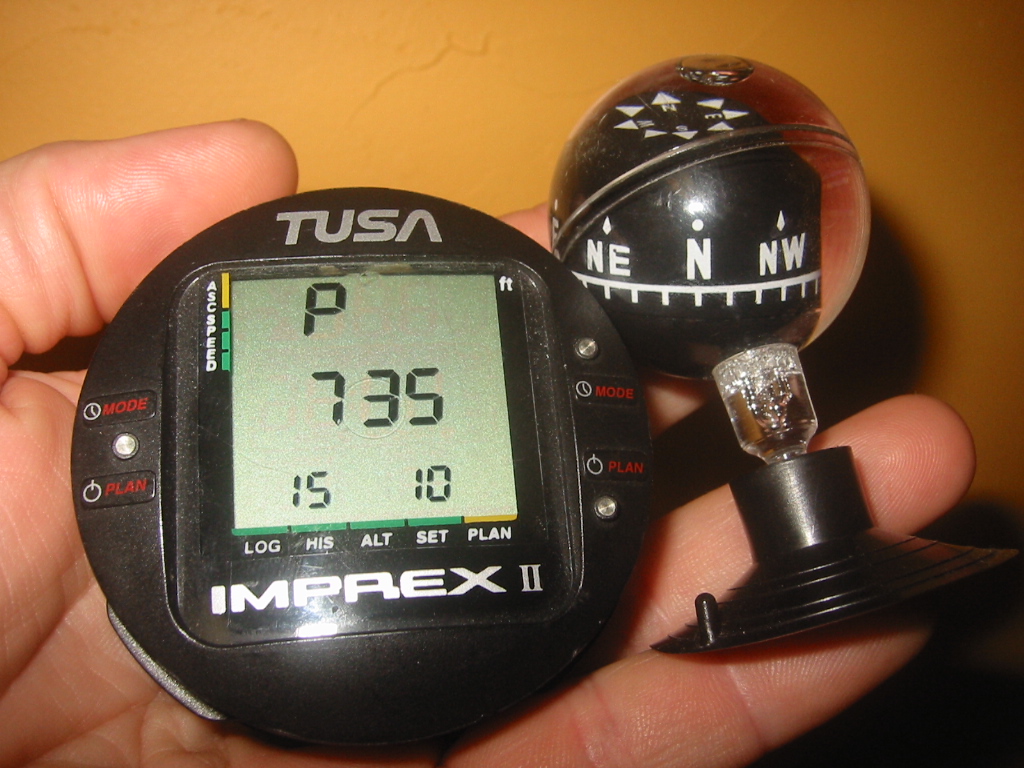
Dive ComputerA common dive computer, like our Tusa Imprex II is a perfect solution for ambient submarines. Just mount it outside the view port and your done. Tusa Imprex II Manual CompassNothing like a good old $1.35 compass on an aluminum or fiberglass boat. Just keep it as far away from wires carrying current as possible, especially wires running vertical.
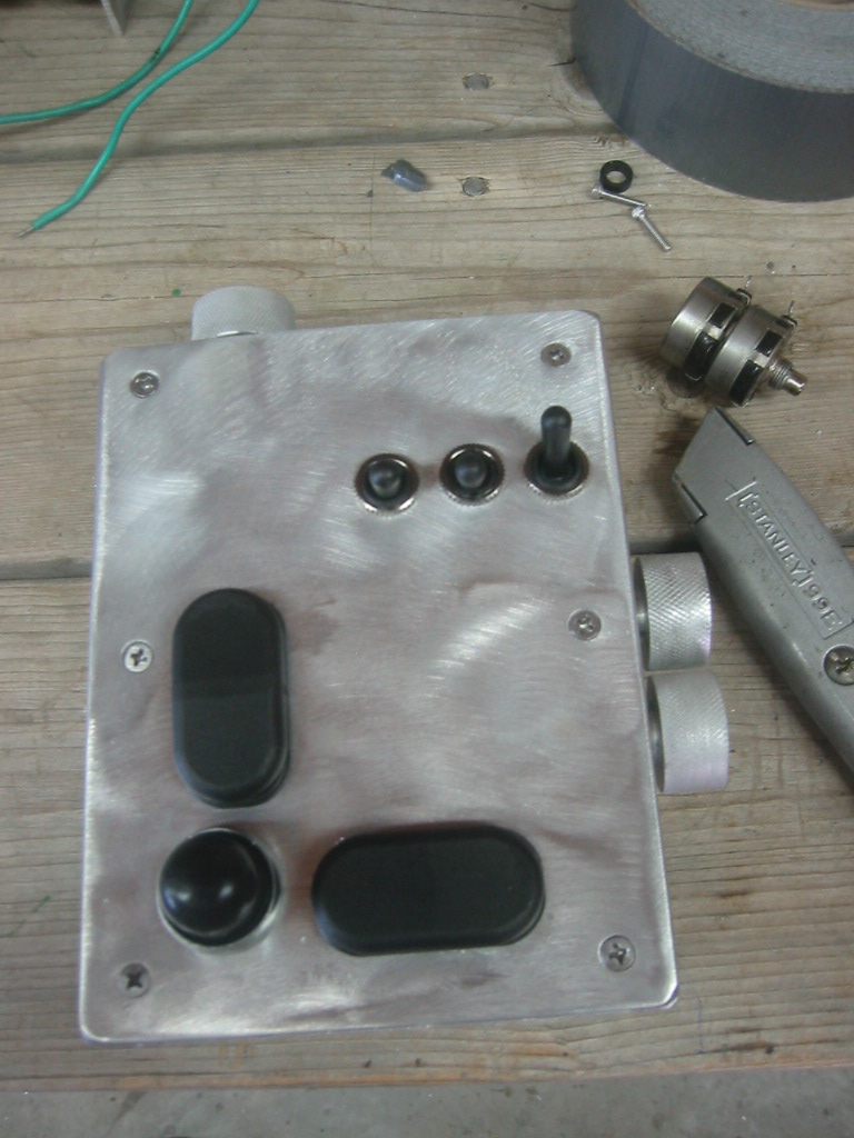
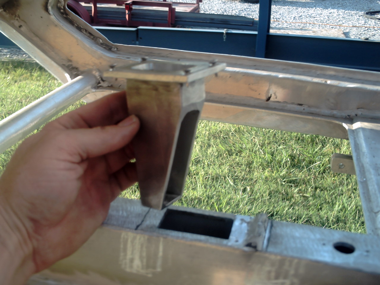
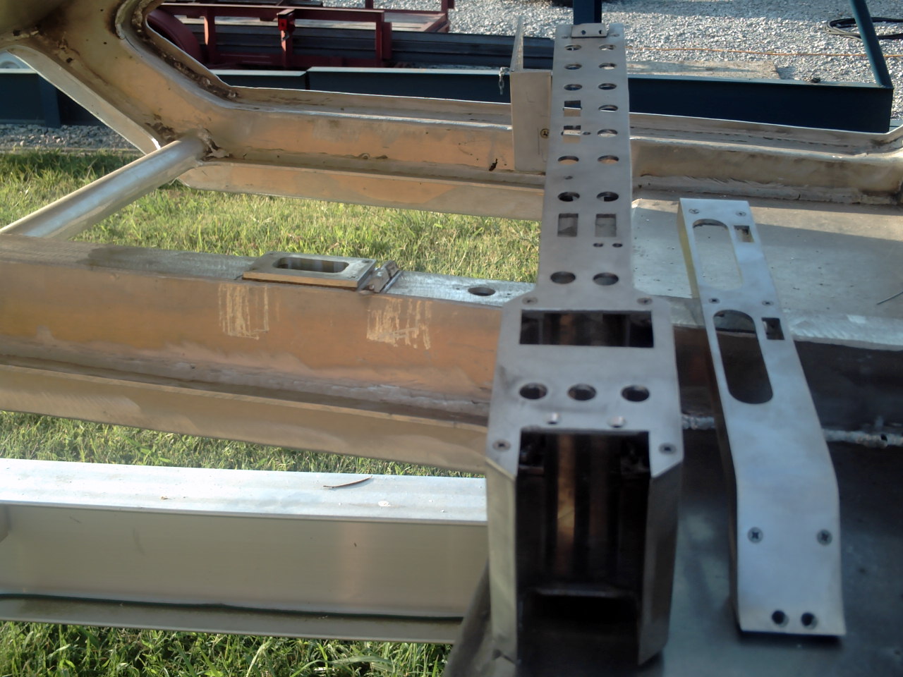
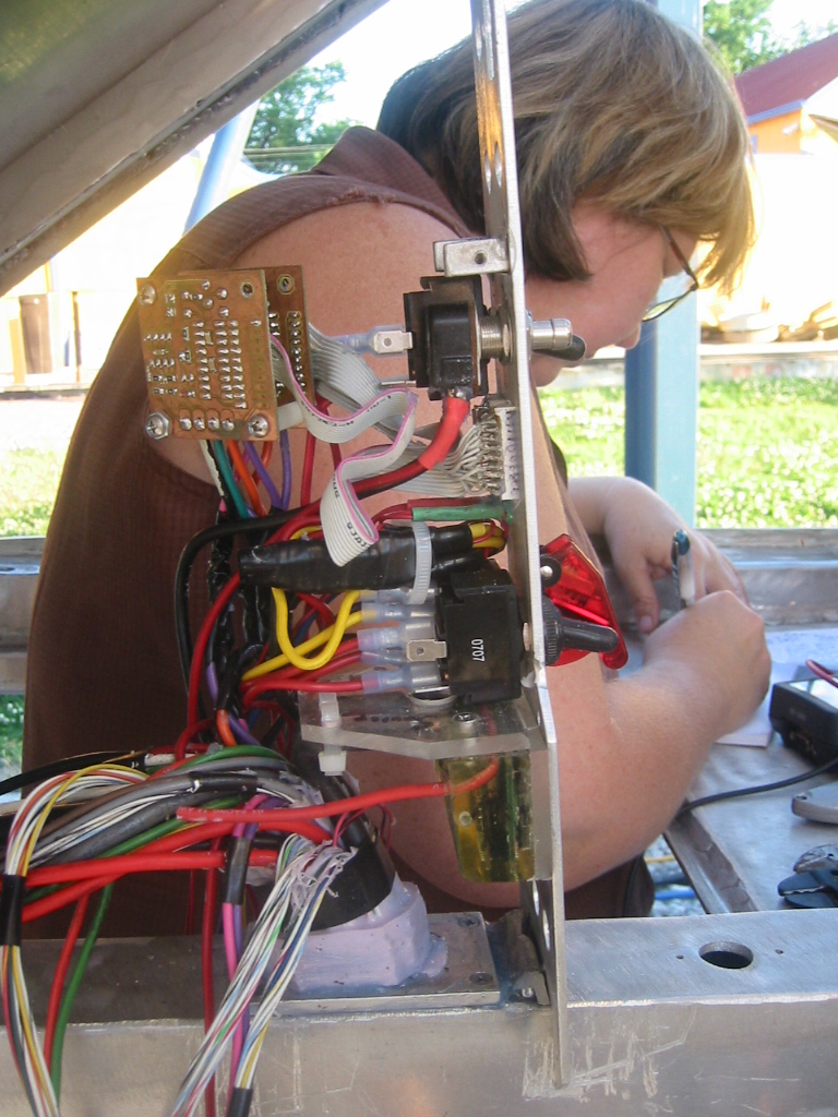
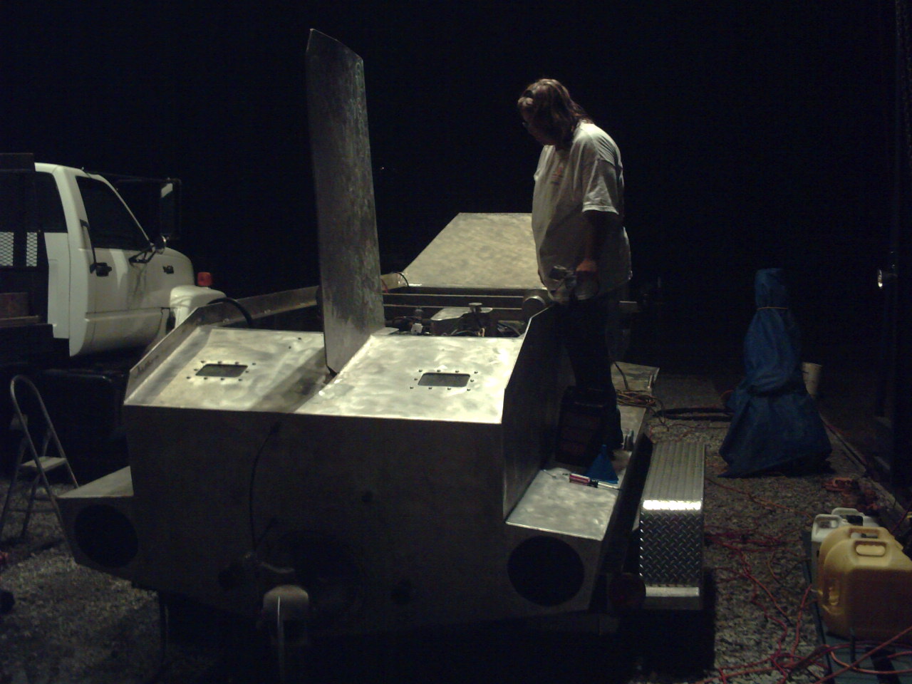
Console(1) The console and the helm control box are where all of the switches are for the wiring system so that is where we will start. However it was the last part designed as it's size is a function of how many switches we need. The console is constructed from 1/8 inch aluminum held together with screws. It will house toggle switches, engine and electrical status indicators.
(2) The helm control box contains additional switches for the engine and thruster controls. There is only enough room in the console and helm control box for the switches and pots. All of the relays, voltage regulators, and speed controllers are water proofed and housed on the backside on of the cabin. The wiring harness from the helm control box passes directly through the cabin wall and is sealed with RTV. This provides enough cable so that the helm control box can be passed through the open top hatch and used while the pilot sits on top of the cabin. (3) (4) The wiring harness from the console passes through a
through hull box that will be sealed with machine wax and then
mounted into the lower center frame of the cabin. From there
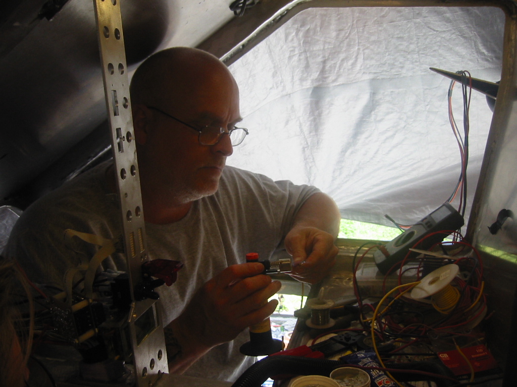
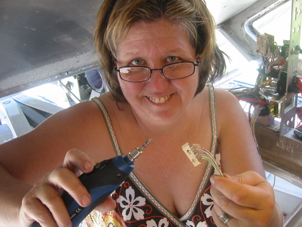
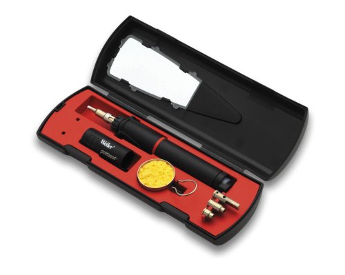
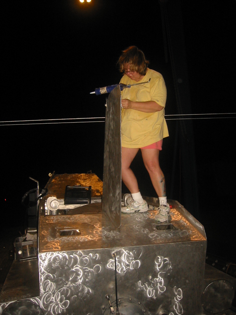
the wiring harness will run to the aft cabin wall. (9) Kay on the other hand has picked up soldering in just 2 days. I can see a lot more of that in her future. And I like the cleavage too. (10) More wires have made it into the console. Last night the landing gear and trim tank actuators went in. This is not all successes. The helm actuator box that moves jet pumps rudder and reverse gate as well as the dive planes refused to do anything, even though we had it working before building the wiring harness. We also tested the thrusters and discovered that the starboard side thruster refuses to switch into reverse. Needless to say there are still a lot of bugs to work out. (11) We are also out of space. I decided that the control boxes for the trim tank linier actuators would be best housed in the center console where they are closer to the control buttons that have more conductors than what goes back to the actuators. However I over estimated how much free space would be left in the center console, so we extended the center console to accommodate the controllers. Soldering IronsI've now gone through my share of under $25 electric and butane soldiering irons from Harbor Freight, Lowes and Home Depot. I really like the butane irons because I don't have to find an extension cord and they heat up much faster than the plug in electric models, and last longer and can put out considerably more watts than the battery powered irons. But there are a lot of cheep butane irons out there, so I broke down and asked guys who use irons in the field routinely which one I should get, and the advice was the Weller P2KC.
|
|||||||||||||||||||||||||||||||||||||||||||||||||||||||||||||||||||||||||||||||||||||||||||||||||||||||||||||||||||||||||||||||||||||||||||||||||||||||||||||||||||||||||||||||||||||||||||||||||||||||||||||||||||||||||||||||||||||||||||||||||||||||||||||||||||||||||||||||||||||||||||||||||||||||||||||||||||||||||||||||||||||||||||||||||||||||||||||||||||||||||||||||||||||||||||||

|
||||

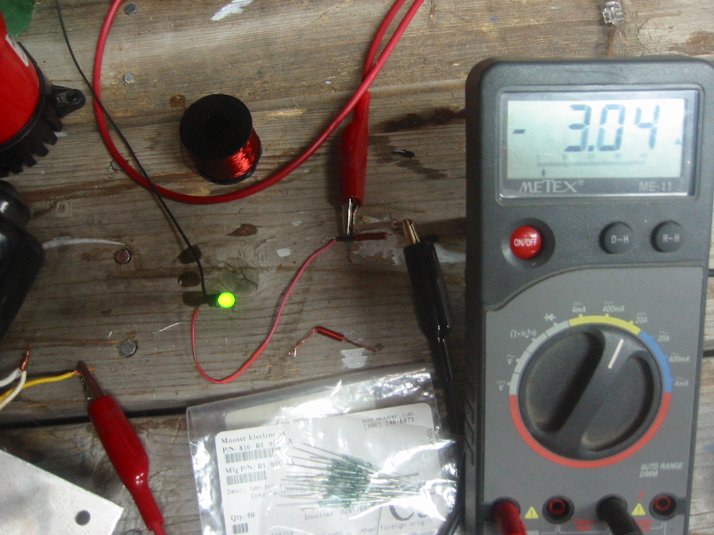
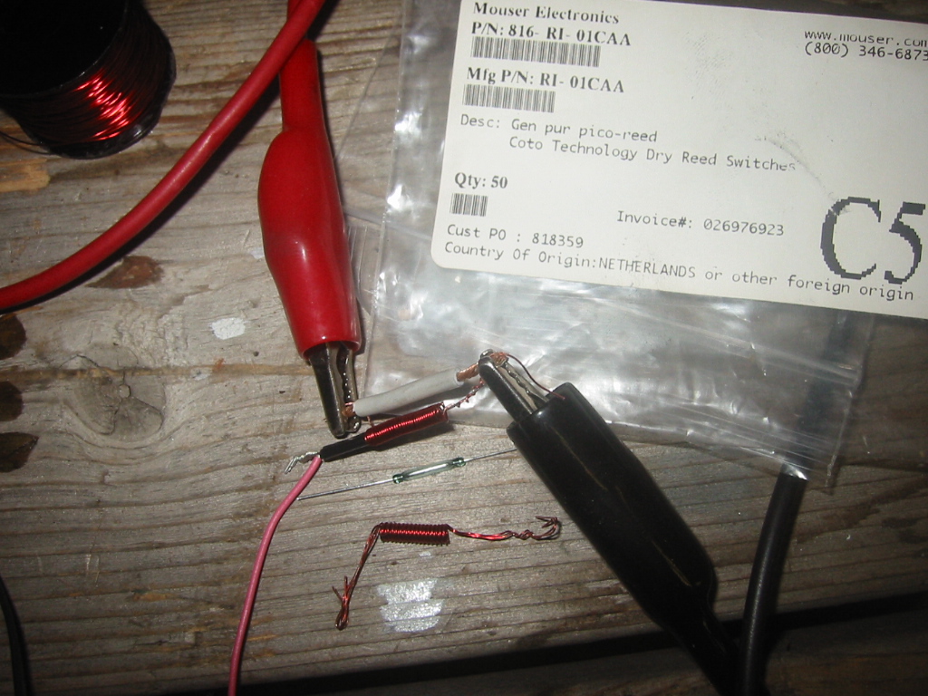
(1) On for the first challenges was to figure out how to get an LED to light only when the jet pump flood valve was moving. There is a DPDT limit switch back on the valve the powers it off once the valve has changed positions, so it's not just a matter of tapping onto the switch. After several failed attempts and a few that sort of worked. I came across a solution using copper enameled wire to make a magnetic coil that closes a read switch which turns on the LED. A single strand of perhaps 30 awg enameled wire stolen from a solenoid coil could wrap more that 30 times around the miniature reed switch but it got too hot with 36 watts. Two strands with about 12 wraps worked too and did not have the heat problem.
(2) (3) However just for kicks I used a piece of 14 awg wire as a jumper across the single stand coil and the dame thing still worked perfectly. I seemed as if the coil only needed a fraction of the amperage. With the 14 awg jumper in place there must be less than 5 watts of power flowing through the coil. I am looking for a better explanation.
Stuff Connected to the Consoles
Engine Starting
|
The wiring will consist of one on-off toggle switch to engage the glow plug controller and kill the engine mounted in the Helm control box, a second momentary on-off toggle switch to start the engine mounted on the console, and an LED indicator lamp powered off the glow plug circuit on the console beside the start switch.
Summary
|
Engine Warning Lights
|
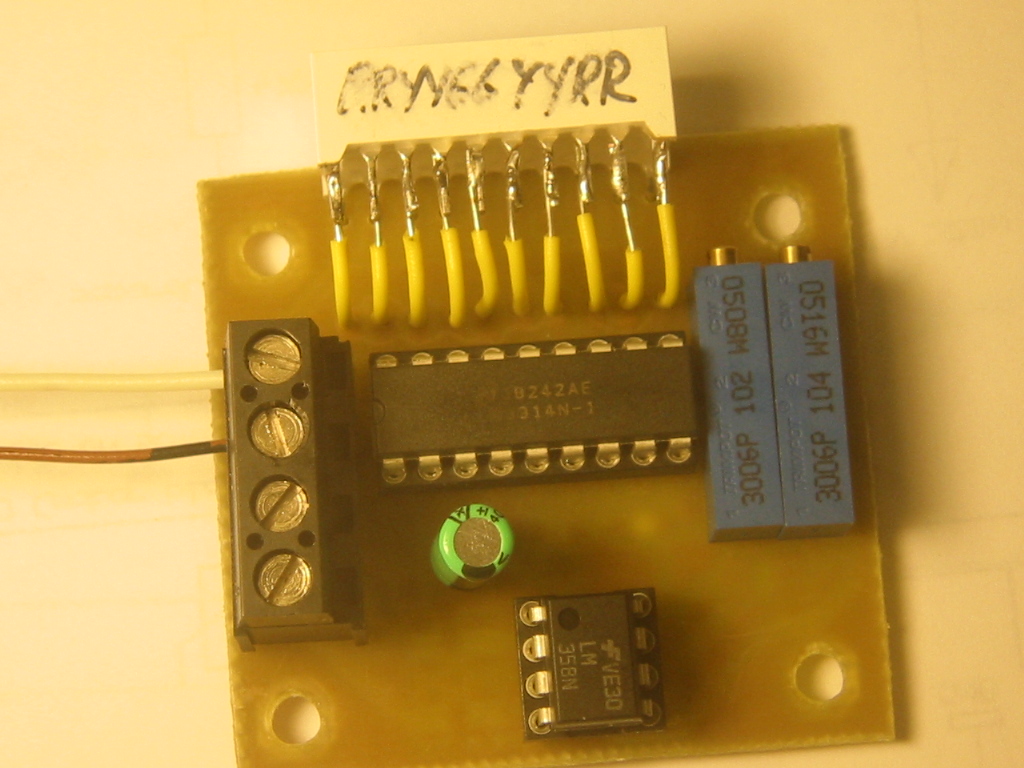
One 10 LED bar graph indicator displays engine temperature, and another displays the oil pressure. The engine sensors simply change resistance with the temperature and pressure, and those are each connected to a small card which converts the change in resistance to a change in voltage and displays the change by lighting more or fewer LED's on the display.
Summary
|
Engine Throttle
|
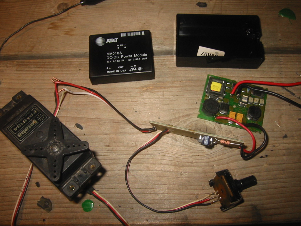
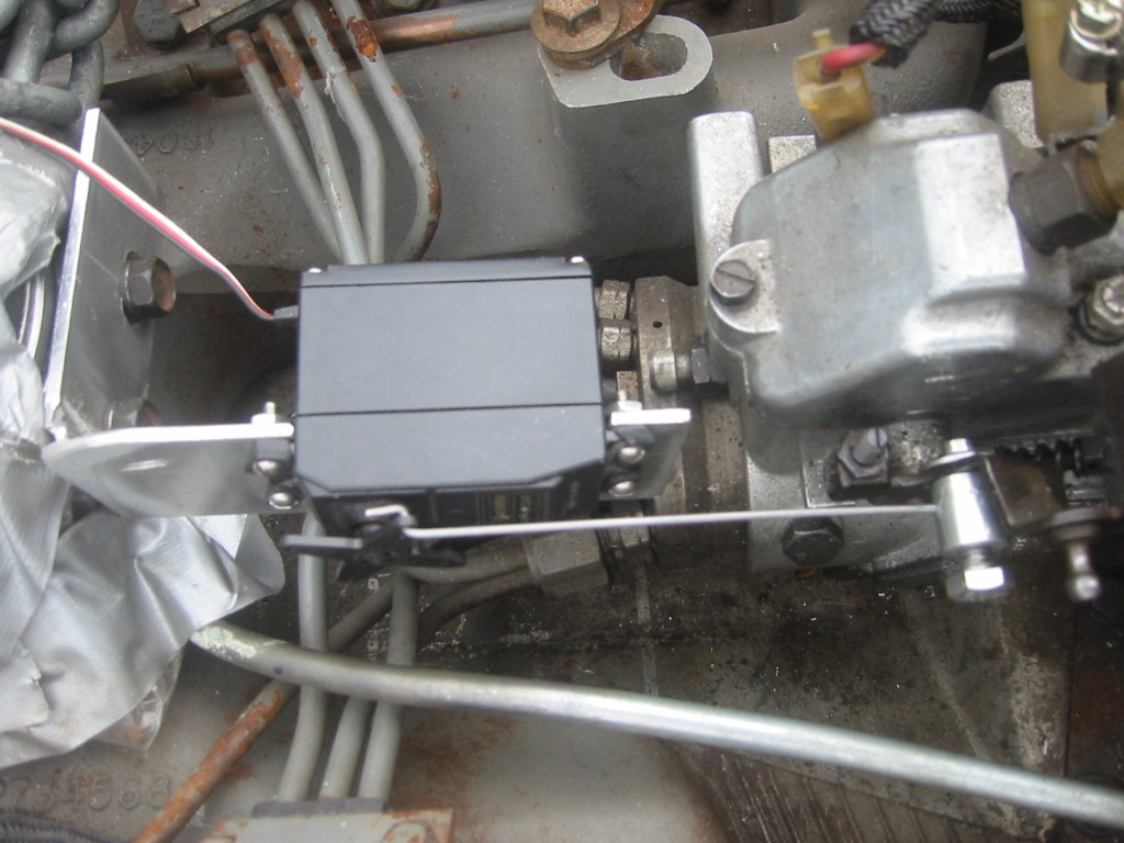
The engine throttle is operated by an RC servo that is controlled by a servo tester. Servo tester circuits are easy to build but they also cheap to buy.
It may be necessary to add a noise trap because of the long servo leads: www.uoguelph.ca/~antoon/gadgets/noiserx.htm If that is the case then the trap can be located inside the engine compartment.
Read more here:
Engine Throttle
Control
Summary
|
|
|
|
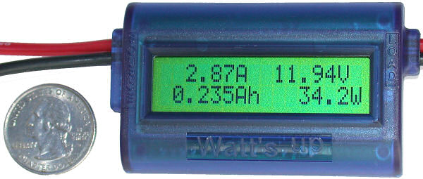
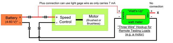
(1) The $60 "Watt's Up" is a digital DC Ammeter, Amp Hour & Watt
Hour Meter. It will measure eight DC values:
* Amp-Hours: (0 - 65)
* Watt-hours: (0 - 6554)
* Amps: (0-100 peak)
* Watts: (0 - 6554)
* Peak Amps & peak Watts
* Minimum voltage ("sags")
* Voltage: (0 - 60)
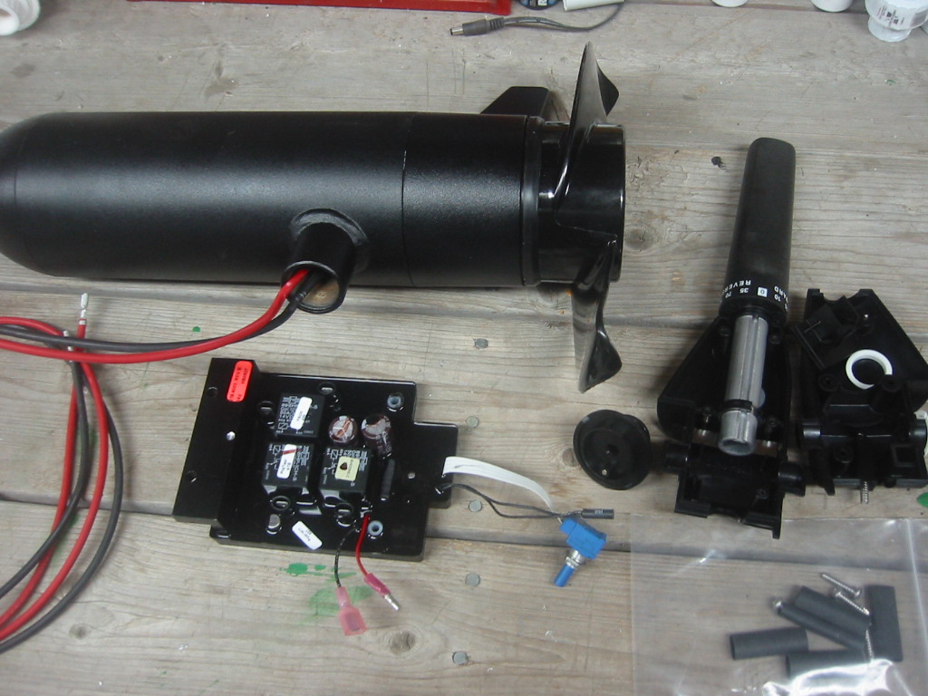
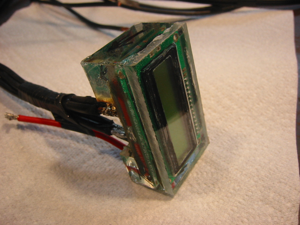
(2) It's rated for continuous duty at 50 amps which is more than half throttle but in the process of water proofing the unit, I removed the case and replaced 12 gauge wire with dual #4 gauge wires and left the solder connections and shunt exposed to the air. The larger wire will act as an excellent heat sync.
(3) There are several ways to wire in the "Watt's Up" ammeter. The best approach for the sub is to use the 3-wire configuration. The negative from the battery connects via the #4 cable to the left hand side of the meter; as you face it's front. The right hand side goes to the load. The red wire on the source side needs 36v positive for use by the ammeter.
Water Level Sensors
|


Water level
sensors are needed in the engine snorkel intake to the engine compartment
to insure that ambient air pressure in the compartment is preventing
the compartment from flooding. Water depth sensors are also
needed in each
of the two soft ballast tanks.
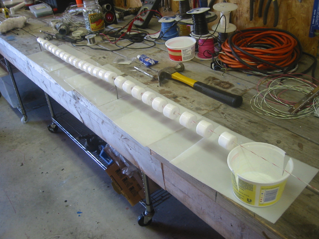
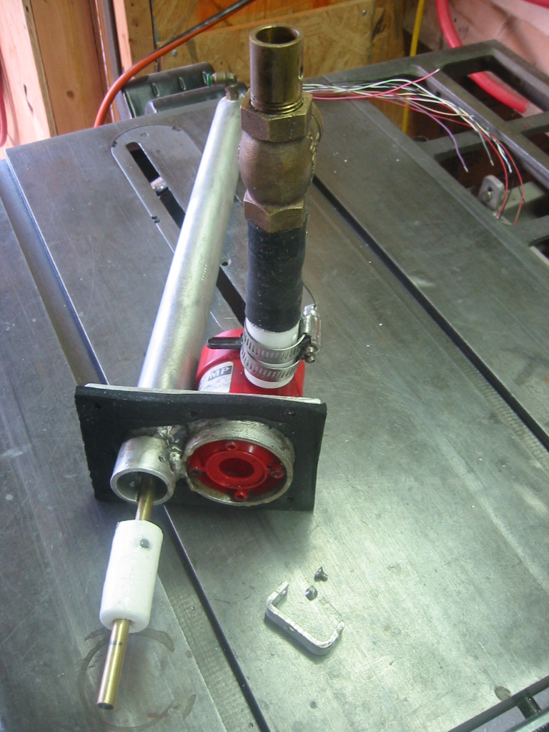
(1) The sensors use float cut from Styrofoam with a hot wire cutter.
(2) 1/8" diameter by 1/2" long bar magnets where then glued into the
floats and the floats were coated with epoxy to make them more
durable. (3) The magnets cause reed switches to close.
(4) The reed switches are inside of a 5/16 inch brass tube that
passes through the center of each float.
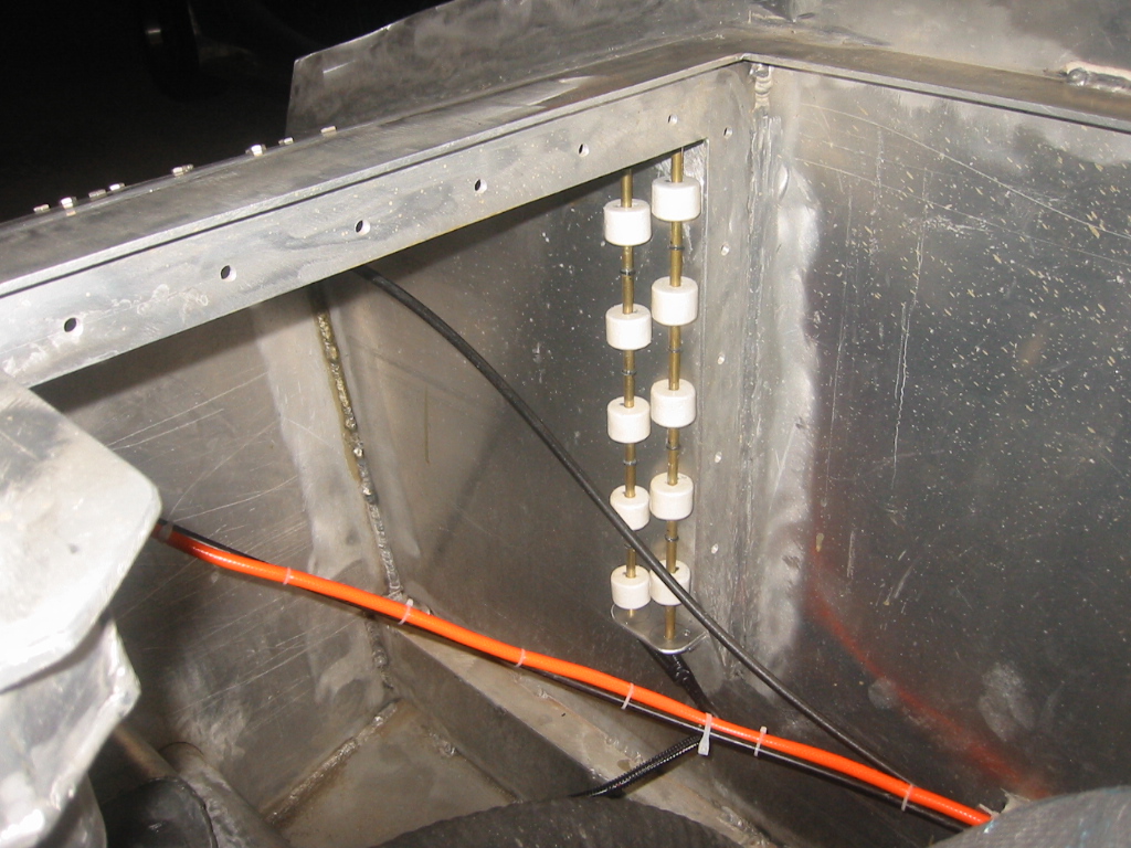
(4) (5) The ballast tank sensors each have one float per reed
switch. Small o-rings are glued in place on the brass rod to
act as limits for the floats and the magnets on these floats have
their poles parallel to the reed switches. There needs to be about 2
inches between each of the reed switches in order to prevent the 1/2
inch long magnet from triggering more than one switch at a time.
(4) The aft ballast tank sensor is only 16 inches tall, so for
it to accommodate 10 switches it was necessary to use two tubes with
each consecutive switch alternated the tube it was on.
(6) When the float rises beside a reed switch, the switch closes and a corresponding LED on a bar graph in the center console lights to indicate the water depth. Each sensor has it's own 10 LED bar graph.
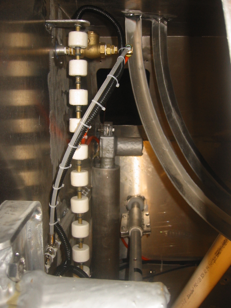
(7) The snorkel sensor only has 1 inch between each reed switch, so it only has one float the triggers one or two reed switches as it rises and falls. The magnets on this float have their north and south poles aligned perpendicular to the reed switches to limit the field.
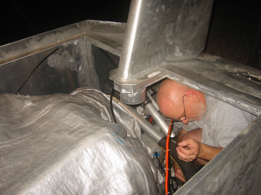
(8) Installing these once again requires squeezing into the smallest spot in the submarine. You pray you don't get a leg cramp when back in the aft.
Summary
|
Snorkel Flood Valve
A 1 inch direct acting 12 volt, 1.5 amp solenoid valve is connected to the bottom of the air intake snorkel just behind the snorkel's bilge pump. It will be opened when submerging so that water can gradually flood into the snorkel. A toggle switch can operate it from the cabin. The valve can remain open while submerged but it should be powered of to conserver the battery once the boat is submerged so the switch will be accompanied by a red LED lamp that indicates that the valve is powered.
Summary
|
Bilge Pumps
|
There are 3 separate areas with bilge pumps: snorkel, engine compartment, and hull. Each area will have it's own on-off toggle switch since each area is dried at different times. When surfacing, the snorkel flood valve and the snorkel bilge pump are both turned on. This allows water to it the snorkel to escape threw the valve by gravity as the snorkel rises above the surface. The valve is then closed and the snorkel bilge is given a minute to empty the water from the snorkel. The engine is then started and any water remaining in the snorkel is drawn into the engine compartment. Once the engine is running then 2 bilge pumps installed in the engine compartment will be started and the snorkel pump will be turned off. Once the jet pump has removed most of the water from the hull, the engine compartment pumps will be turned off a float switch equipped bilge pump in the hull will be turned on and remain on while the boat is surfaced.
Summary
|
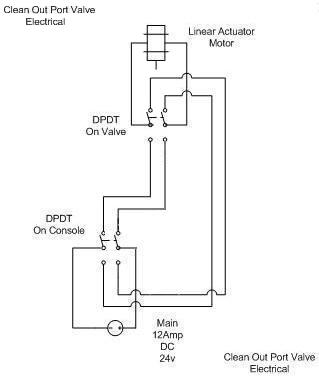
Jet Pump Clean Out Port Valve
|
|
2 - Two position DPDT, or on-on toggle switches. One acts as a limit switch on the linier actuator that opens and closes the clean out valve on the jet pump, and the other in the cockpit to trigger the valve to open or close. This is a very simple setup, the only one draw back is that once the valve has started moving it must complete the movement in that direction of travel before it can be reversed. Hence the toggle switch in the cockpit needs to have a safety latch to protect it from invariantly being flipped at the wrong time.
Summary
|
Landing Gear
|
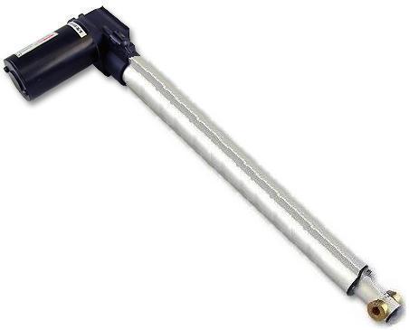
4 - Toggle switches to control the 4 linier actuators that will extend and retract and perform the function of landing gear by lowering down legs for the sub to come to rest on when settling to the bottom. The additional height off the bottom makes it possible for the occupants to open hatches under their feet and exit the cabin. The actuators are12 volt DC, 30 inch stroke, 400 lb (Static) load, aluminum shaft, with fixed limit switches. Approx 5 amps at full load. They take about 35 seconds to deploy or retract.
Summary
|
Ballast/Battery Sled
|
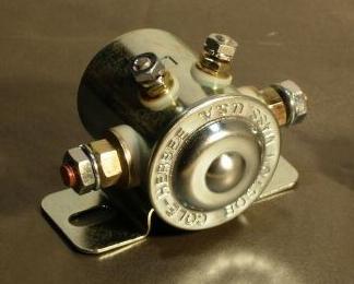


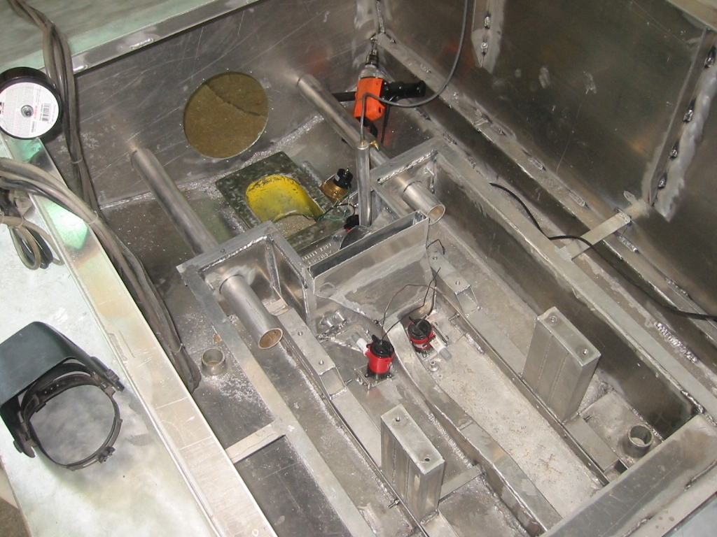
(1) The electronics on the winch consist of 2, SPDT (Single Pole Double Throw) solenoid relays that control direction. (2) (3) I added a third SPST relay on the positive lead for added safety. The third relay will allow power to be disconnected with an on-off toggle switch in the cabin, just in case one of the other relays sticks on.
The control box has since been revised after the failure of the potting damaged one of the solenoids. The two SPDT solenoids which controlled direction of travel have been replaced by a integrated reversing relay from www.texasindustrialelectric.com, They are $24 on ebay. Also eliminated the red and yellow power conductors going to the console. Instead control power to the relays will come from a common 12 volt fee to the console.
The winch mounts onto the rear of the battery and ballast sled so power will come directly from the 12 volt battery system. The cockpit will have 1 on-off toggle for the power on relay, and 1 momentary on-off-on toggle for controlling the direction of travel.
Limit switches will be installed at both ends of the sled track. These will consist of reed switches with magnets attached to leavers that normally rest on the reed switch. When the sled reaches is limit of travel it will push the leaver and the magnet away from the reed switch causing the switch to open and the solenoid of that direction of travel to power off.
Along the side of the track there will be 10 normally open leaver activated switches, and as the sled moves along it will move the leaver of the switch beside it and illuminate the corresponding LED on a 10 LED bar graph on the console.
|
|
(6) (7) I got a great deal on some reed switches that are potted in a small housing with a magnet and spring loaded arm that pushes the magnet up beside the reed switch. Only problem is that the arm only worked from one direction so Kay modified the arm with a glued on piece of acrylic that allows the arm to be lifted from both directions.
Summary
|
Soft Trim Tanks
The forward and aft soft trim tanks will each be regulated by a linear actuator. Each actuators is connected to a vent pipe in trim tank. Moving the vent higher in the tank vents more air and reduces buoyancy and lowering it will increase buoyancy. Air flowing slowly through the system from the high pressure tanks displaces the water in the trim tank until it again starts escaping from the vent pipe. Positioning the actuators to preset positions for positive, neutral, and negative buoyancy is made simple with these actuators designed for positioning car doors. They come with their own control unit and 3 button switch than can make fine adjustments and have the current position recorded so that the actuator returns to the position with one touch. The control module is potted and housed in the cabin console.
For more details see:
Soft Ballast Tanks
Summary
|
Head Lights and Navigation Lights
|
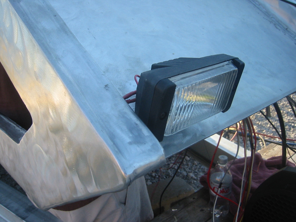

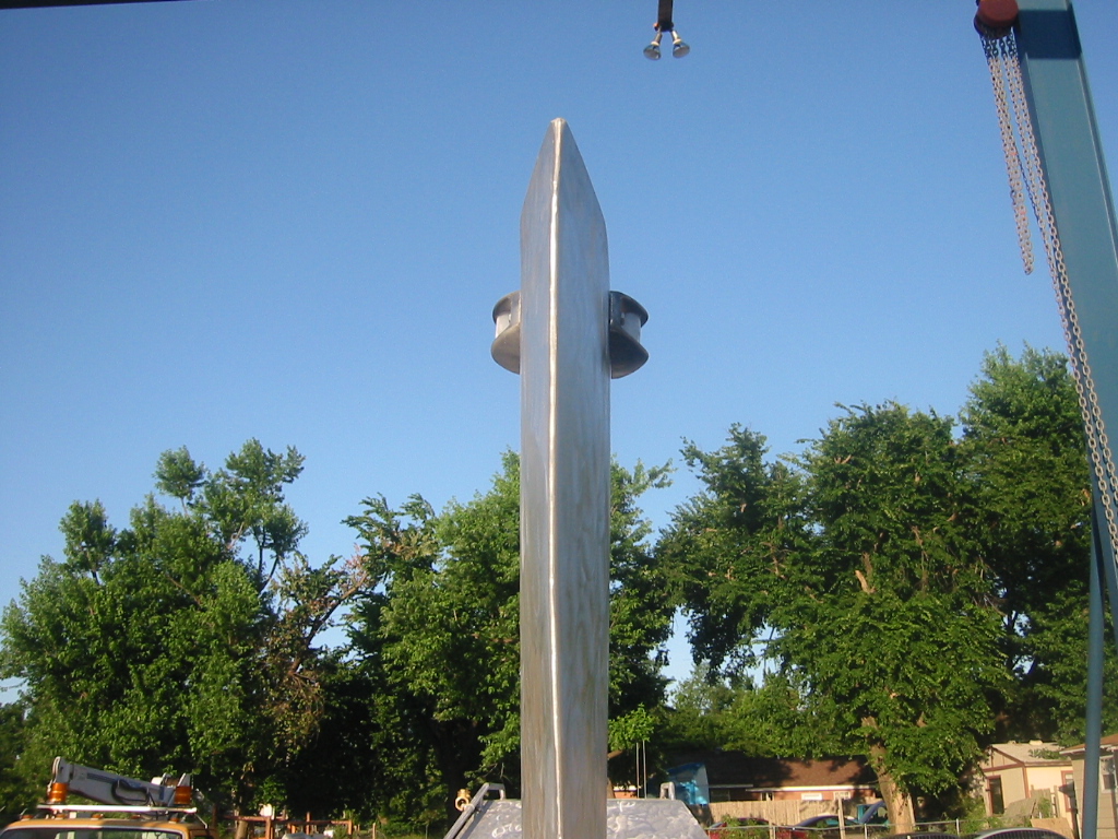
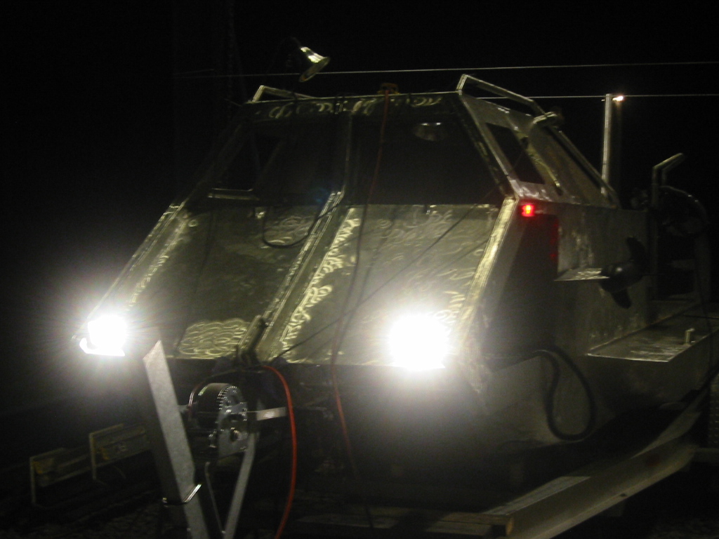
And God said, let there be light; and it was so.
We put a couple of accessory lights on the front. And the
Ford truck we purchased for our sailboat's crane donated
the aluminum housings. The red, port lens is stock but the green
starboard and the white lenses were donated from a plastic drink
bottles.
Wiring Harness Colors
|
||||||
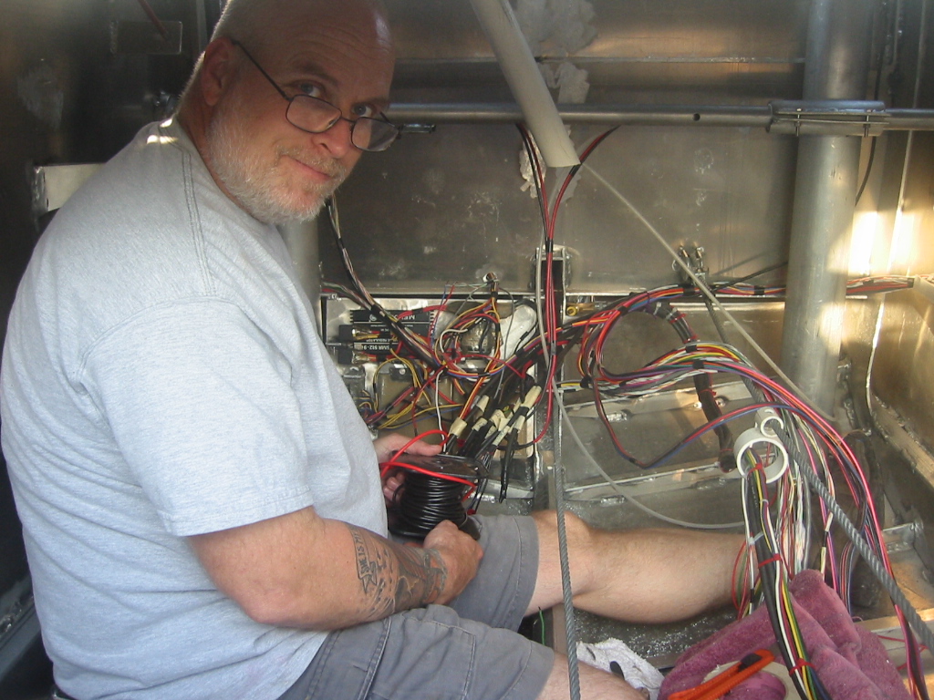
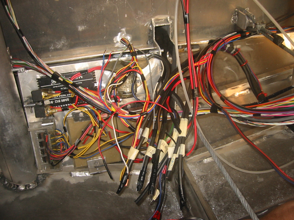
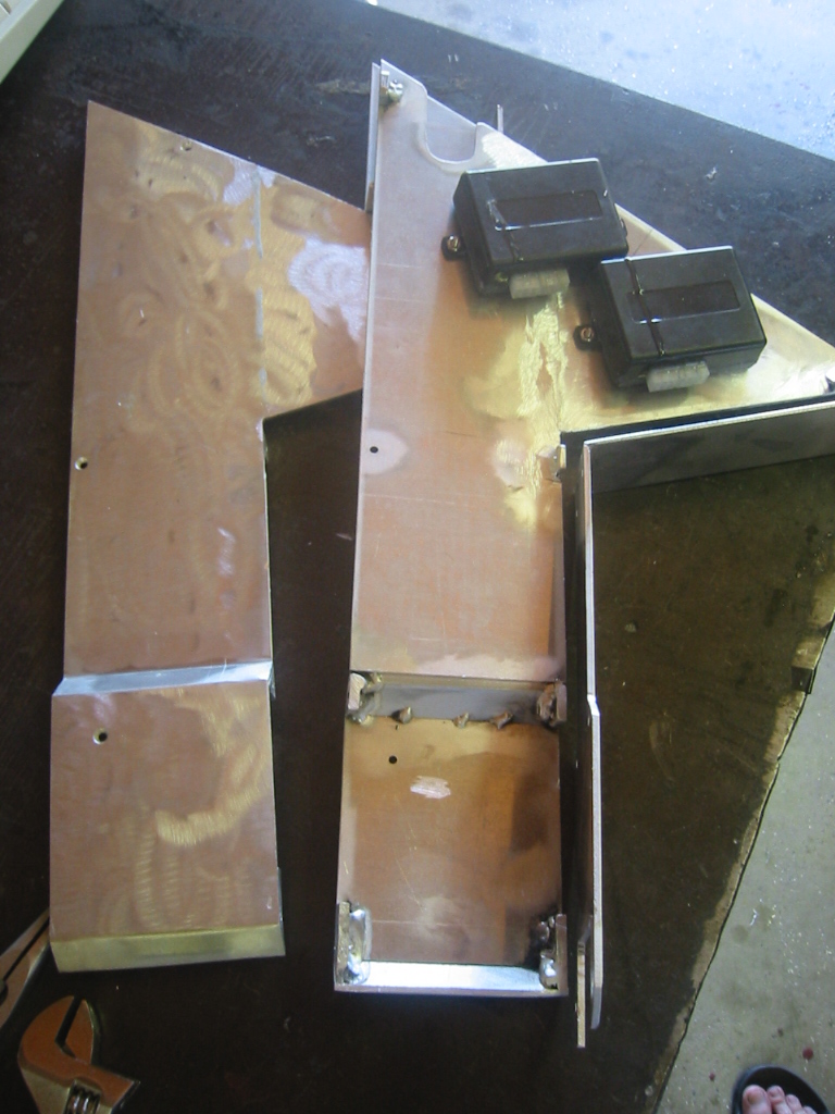
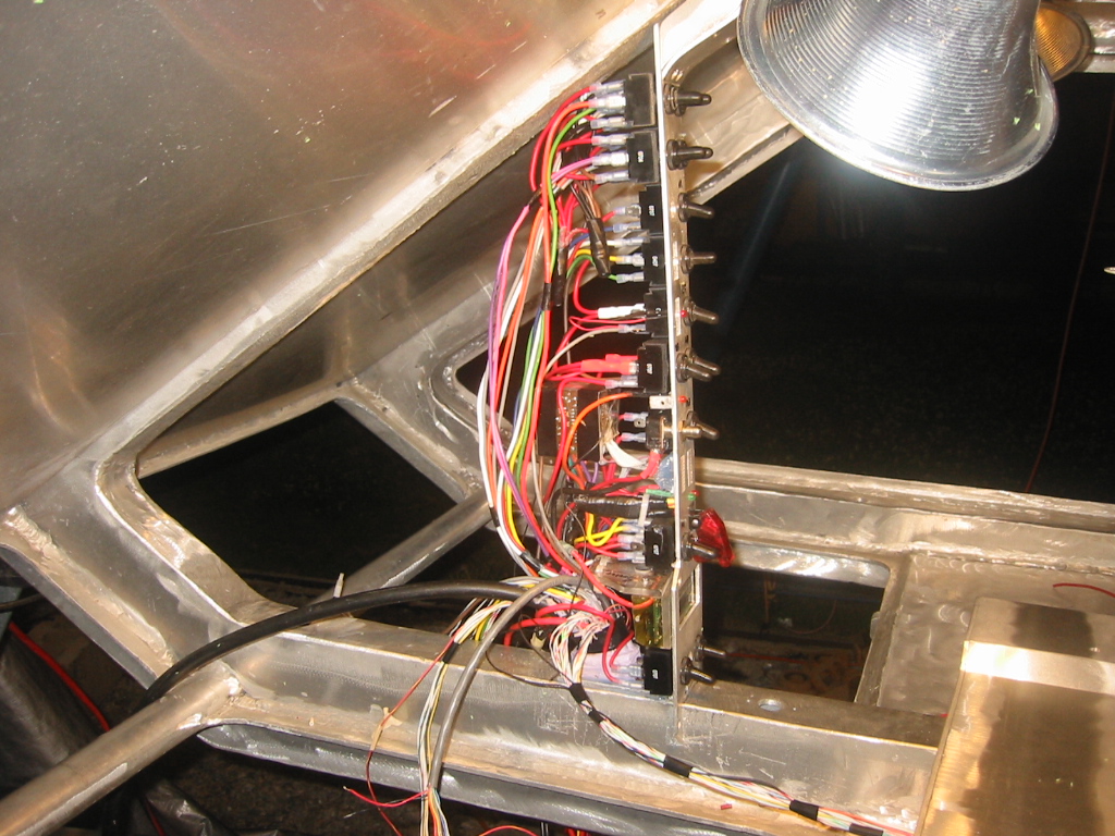
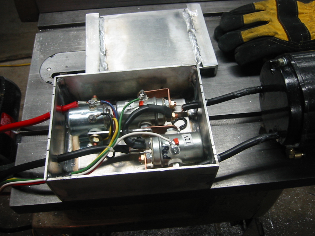
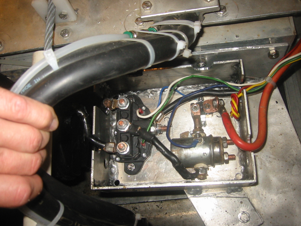
(1) After several nights of cussing and leg craps with the rainbow spaghetti is starting to look more organized. A total of 18 electric motors on board and 58 conductors for position sensors plus other assorted electric stuff makes for a lot of wires. (2) I installed a hinged panel on the back of the cabin and mounted the speed controllers, relays and dc-dc converter there. The whole area is referred to as the "electric junction" as it is the intersection of wiring harnesses from the engine along with other equipment that travels down the starboard side of the hull, another harness that includes snorkel flood, bilge, and the helm actuator box down the port side of the hull. A third coming through the cabin wall from the helm control box, and a forth that travels thought the center frame to the cabin console.
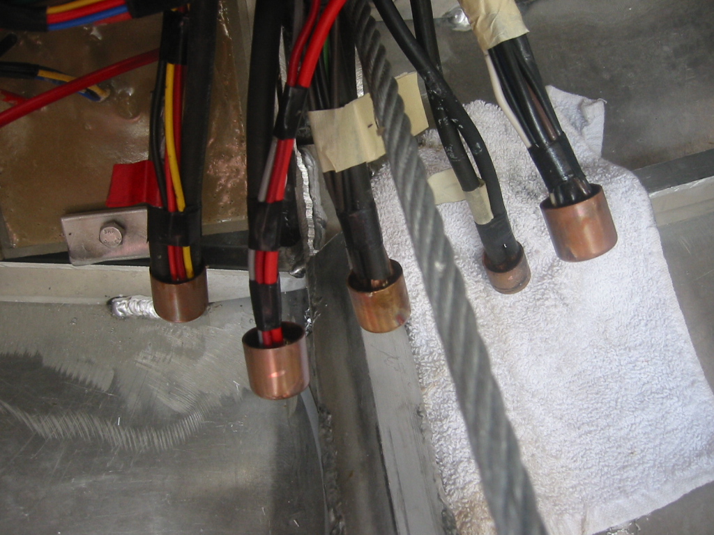
All of the power comes from either the 12v or 36v battery bank. And everything 36v also passes back through the "Watt's Up" ammeter. (3) That makes for five connection points were several cables of various sizes meet. A bus bar would normally be used but that would be a pain to waterproof so instead I use 1/2" copper end caps as solder lugs and incased those in PVC and RTV.
Flux is first smeared onto the stripped wire ends to be connected, then the copper pipe cap is held with vise grips, heated with a torch and solder is melted into the cap until it is half full. Then just plunge the wire ends into the solder and wait for it to harden.
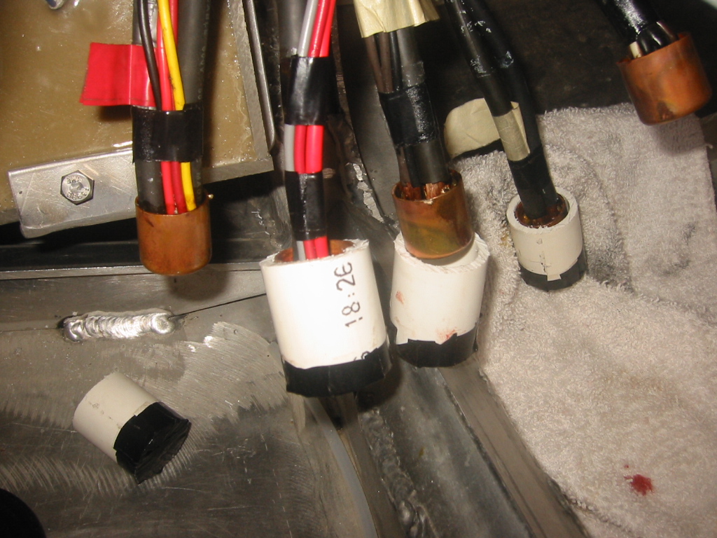
(7) To insulate the connection, a short piece of 1" PVC is cut
and one end taped closed in order to form a mold around the copper
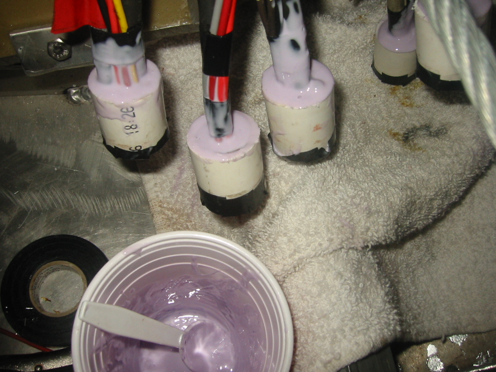
cap for RTV. (8) The RTV is mixed and poured into the PVC mold
and worked so that it flows under the cap as well as in between the
wires. If needed the PVC and RTV can be cut away, and the cap heated
so that a wire can be removed or added. I get my two part RTV
from www.jgreer.com
for about $60 for 1/2 gallon.
|
||||||||||||||||||||||||||||||||||||||||||||||||||||||||||||
|
|||||||||||||||||||||||||||||||||||||||
|
|||||||||||||||||||||||||||||||||||||||
|
|||||||||||||||||||||||||||||||||||||||
|
||||||||||||||||||||||||
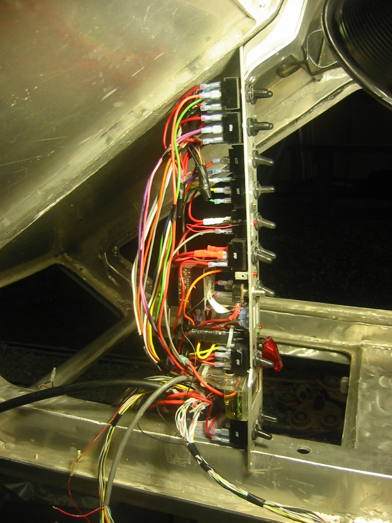
Circuit Breakers - Better than Fuses.
|
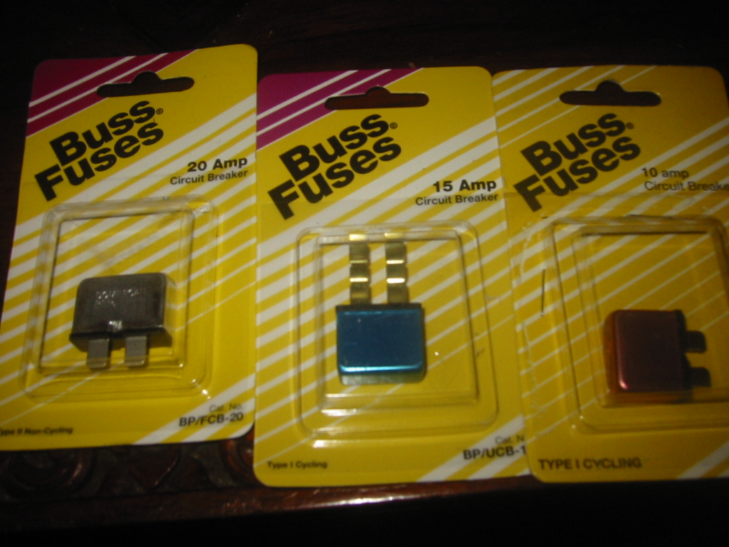
Blade fuses are fine for lots of things, but if you blow a fuse because something was blocking a motor or you just ran it too long, then removing the obstruction or letting it cool down still leaves you with a blown fuse in an otherwise useable system. If you use a circuit breaker circuit breaker instead you will get the uses of the system back without having to find and replace the fuse. Not something that you'll likely be able to do while submerged.
They come in there verities from the auto parts store:
Type 1 auto reset will cycle the circuit breaker until the
overload condition is removed.
Type 2 modified reset will keep the circuit breaker open until the
overload condition is removed.
Type 3 manual reset thermal non-cycling circuit breakers will remain
tripped until the operator resets them by pushing a button located
on the breaker.
Suppliers
www.wiringproducts.com
-- Toggle switches, battery switches, etc. Good customer service
when there was a problem.